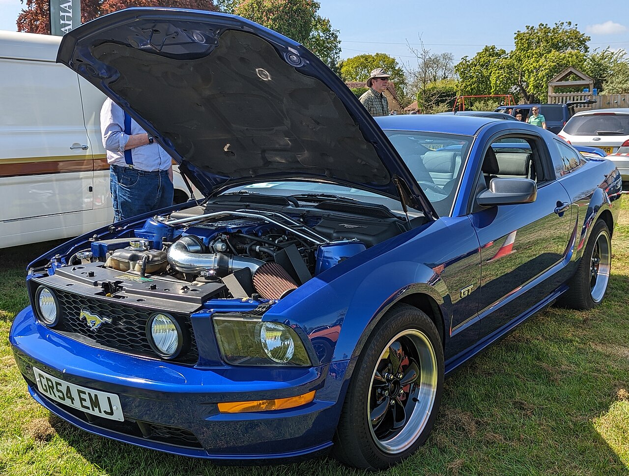
Ford Mustang IV New Edge 1999-2004 uses a passenger-compartment fuse panel and an under-hood power-distribution box. Some circuits differ by model year, V6/V8 engine, Cobra equipment and Mach 460/Mach 1000 audio.
For the next generation, see Ford Mustang S197 2005-2009. Fuse numbers from the S197 do not carry over to the New Edge.
Fuse-box locations
Passenger compartment: under the dashboard on the driver’s side. Engine compartment: the power-distribution box contains the high-current fuses and relays for starter, cooling fan, fuel pump, ABS, PCM, Cobra and Mach 1000 circuits.
Passenger-compartment fuse panel
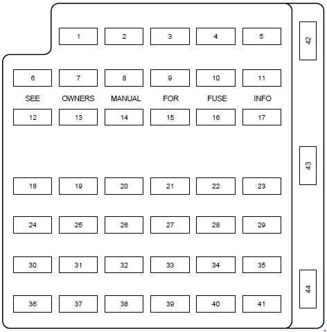
| Position | Rating [A] | Protected component / function |
|---|---|---|
| 1 | 20 | Cigarette lighter / lighter socket. |
| 2 | 20 | Engine control. |
| 3 | – | Not used. |
| 4 | 10 | Right headlamp. |
| 5 | 15 | Instrument cluster, traction-control switch. |
| 6 | 20 | Starter relay. |
| 7 | 15 | GEM, interior lighting. |
| 8 | 20 | Engine control. |
| 9 | 30 | 2002-2004: Mach 460 subwoofers. |
| 10 | 10 | Left headlamp. |
| 11 | 15 | Rear lamps. |
| 12 | 2 | 2003-2004: heated PCV system. |
| 13 | 15 | Electronic turn-signal flasher. |
| 14 | – | Not used. |
| 15 | 15 | Power lumbar adjustment. |
| 16 | – | Not used. |
| 17 | 15 | Speed-control servo, shift interlock. |
| 18 | 15 | Electronic turn-signal flasher. |
| 19 | 15 | Power mirrors, GEM, power locks, anti-theft system, door-ajar switches. |
| 20 | 15 | Convertible-top control. |
| 21 | 5 | Instrument-cluster and engine-control memory. |
| 22 | – | Not used. |
| 23 | 15 | A/C clutch, heated-rear-window switch. |
| 24 | 30 | Blower motor. |
| 25 | 25 | Electric decklid release. |
| 26 | 30 | Wiper motor and relays. |
| 27 | 25 | Radio. |
| 28 | 15 | GEM, overdrive cancel. |
| 29 | 15 | ABS module. |
| 30 | 15 | Daytime Running Lamps module. |
| 31 | 10 | Data Link Connector / OBD-II. |
| 32 | 15 | Radio, CD player on 1999-2001, GEM. |
| 33 | 15 | Brake-light switch, speed-control switch. |
| 34 | 20 | Instrument cluster, CCRM, Data Link Connector, PATS. |
| 35 | 15 | Shift interlock, PCM, speed control, ABS. |
| 36 | 15 | Airbag module. |
| 37 | 10 | Adjustable interior illumination. |
| 38 | 20 | Headlamps. |
| 39 | 5 | GEM. |
| 40 | – | Not used. |
| 41 | 15 | Stop lamps. |
| 42 | – | Not used. |
| 43 | 20 | Power-window circuit breaker. |
| 44 | – | Not used. |
Engine-compartment power-distribution box
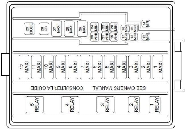
| Position | Rating [A] | Protected component / function |
|---|---|---|
| 1 | 30 / 50 | Radiator cooling fan – 30 A V6, 50 A V8. |
| 2 | 30 | Headlamps. |
| 3 | 40 | Starter, ignition switch. |
| 4 | 40 | Ignition switch. |
| 5 | 40 | Ignition switch. |
| 6 | 40 | Passenger-compartment fuse panel, instrument cluster, PCM. |
| 7 | 30 | 1999-2002: secondary air injection – 3.8 V6. |
| 8 | 50 | ABS module. |
| 9 | 20 | Auxiliary power point. |
| 10 | 30 | Parking lamps. |
| 11 | 30 | Heated rear window. |
| 12 | 40 | Power windows 1999-2002, power locks. |
| 13 | 30 | 2003-2004: right-side Mach 1000 amplifiers. |
| 14 | 20 | Fuel pump. |
| 15 | 10 / 30 | 1999-2002: radio – 10 A; 2003-2004: left-side Mach 1000 amplifiers – 30 A. |
| 16 | 20 | Horn. |
| 17 | 20 | ABS. |
| 18 | 25 | Power seats. |
| 19 | 10 | 2002-2004 Cobra: intercooler pump. |
| 20 | 20 | Alternator. |
| 21 | – | Not used. |
| 22 | – | Not used. |
| 23 | – | Not used. |
| 24 | 20 | A/C pressure circuit. |
| 25 | – | Not used. |
| 26 | 30 | PCM. |
| 27 | 20 | DRL module, fog-lamp relay. |
| 28 | 25 | Convertible-top circuit breaker. |
| R1 | Relay | Fog-lamp cutout. |
| R2 | Relay | Wipers. |
| R3 | Relay | Wiper high / low speed. |
| R4 | Relay | Starter. |
| R5 | Relay | Fog lamps. |
Commonly checked circuits
- Cigarette lighter: cabin position 1 – 20 A.
- OBD-II / DLC: cabin position 31 – 10 A; position 34 also includes the diagnostic connector circuit.
- Fuel pump: under-hood position 14 – 20 A.
- Cobra intercooler pump: under-hood position 19 – 10 A on 2002-2004 Cobra.
FAQ – Ford Mustang 1999-2004 fuses
Why does under-hood position 15 have two different ratings?
On 1999-2002 cars it is a 10 A radio circuit. On 2003-2004 cars with Mach 1000 it can be a 30 A feed for the left-side amplifiers.
Does the same cooling-fan fuse apply to V6 and V8?
No. Under-hood position 1 is listed as 30 A for V6 and 50 A for V8.