Mercury Sable 1996-1999 uses a passenger-compartment fuse panel and an engine-compartment power distribution box. The 1996 under-hood layout differs from the 1997-1999 arrangement, so both are shown separately.
Several circuits also vary by model year inside the cabin panel. The duplicated position 32 is intentional: it is rated 5 A in 1996 and 10 A in 1997-1999.
For the next generation, see Mercury Sable 2000-2005.
Passenger-compartment fuse panel
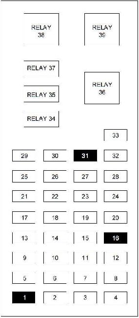
| Position | Rating [A] | Protected component / function |
|---|---|---|
| 1 | – | Not used |
| 2 | 5 | Instrument illumination |
| 3 | 10 | Left low beam |
| 4 | 10 | Right low beam |
| 5 | 5 | Instrument cluster, shift actuator, rear defrost |
| 6 | 15 | Transmission-range sensor, reversing lamps, daytime running lamps, climate controls, MLPS switch, speed control |
| 7 | 10 | Transmission-range sensor, starter relay, MLPS switch |
| 8 | 5 | Power antenna, radio control module, GEM |
| 9 | 10 | ABS, central temperature monitor |
| 10 | 20 | PCM relay, ignition coil, radio, Passive Anti-Theft System |
| 11 | 5 | Instrument cluster, airbag indicator |
| 12 | 5 | Instrument cluster, autolamps, transmission-control switch, Integrated Control Panel, GEM |
| 13 | 5 | Electronic control module, blower motor, airbag, electronic automatic temperature control |
| 14 | 5 | Air suspension, lamp-out indicator – 1996-1997 |
| 15 | 10 | Multifunction switch – turn signals |
| 16 | – | Not used |
| 17 | 30 | Front wiper / washer |
| 18 | 5 | Headlamp switch |
| 19 | 15 | Rear wiper / washer |
| 20 | 5 | Integrated Control Panel, remote entry, cellular phone, GEM – 1999 |
| 21 | 20 | Cigarette lighter |
| 22 | 5 | Power mirrors, power antenna, luggage-compartment lamp, autolamp |
| 23 | 5 | GEM, wiper system, variable-assist steering, remote entry, anti-theft system |
| 24 | 5 | RCC, speedometer, Integrated Control Panel, electronic automatic temperature-control module |
| 25 | 10 | Data Link Connector (DLC) |
| 26 | 15 | Luggage compartment |
| 27 | 10 | Battery-saver relay |
| 28 | 15 | Speed control, stop lamp |
| 29 | 15 | Multifunction switch, hazard lamps |
| 30 | 15 | High beams, daytime running lamps, instrument cluster |
| 31 | 5 | Rear-lamp supply |
| 32 | 5 | 1996: Integrated Control Panel, heated mirrors |
| 10 | 1997-1999: Integrated Control Panel, climate control, heated mirrors | |
| 33 | 5 | Power windows, lock illumination |
| Relay | ||
| 34 | Relay | Battery-saver relay |
| 35 | Relay | Driver-door unlock relay |
| 36 | Relay | Rear-window defrost relay |
| 37 | Relay | Interior-lamp relay |
| 38 | Relay | Driver one-touch-down window relay |
| 39 | Relay | Delayed accessory relay |
Engine-compartment power distribution box – 1997-1999
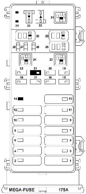
| Position | Rating [A] | Protected component / function |
|---|---|---|
| 1 | 40 | Passenger-compartment fuse panel |
| 2 | 30 | PCM relay |
| 3 | 40 | Ignition relay, starter relay |
| 4 | 30 | Circuit breaker: delayed accessory relay, power windows, left/right power seats |
| 5 | 40 | Ignition switch |
| 6 | 30 | 1997-1998: left/right power seats. 1998-1999: not used |
| 7 | 40 | Rear-window defrost relay |
| 8 | 30 | Thermo-electric air-bypass coil, EAM solid-state relay |
| 9 | 40 | High-speed and low-speed cooling-fan relays |
| 10 | 20 | Fuel-pump relay |
| 11 | 40 | Blower-motor relay |
| 12 | – | Not used |
| 13 | 40 | ABS module |
| 14 | – | Not used |
| 15 | 15 | Daytime Running Lamps module |
| 16 | 10 | 1997-1998: airbag diagnostic monitor. 1999: electronic control unit |
| 17 | 20 | Rear control unit, CD changer |
| 18 | 30 | ABS module |
| 19 | 15 | Horn relay, Powertrain Control Module |
| 20 | 15 | Headlamp relay, autolamp parking-lamp relay |
| 21 | – | Not used |
| 22 | 30 | Autolamp relay, multifunction switch, headlamp switch |
| 25 | – | A/C clutch relay |
| 26 | 30 | Generator / voltage regulator |
| 27 | 10 | A/C clutch relay |
| 28 | 15 | Heated oxygen sensors, canister vent |
| Diode | ||
| 32 | Diode | PCM diode |
| 33 | Diode | A/C clutch diode |
| 34 | Diode | Not used |
| Relay | ||
| 23 | Relay | Blower-motor relay |
| 24 | Relay | Starter relay |
| 29 | Relay | Fuel-pump relay |
| 30 | Relay | PCM relay |
| 31 | Relay | Low-speed cooling-fan relay |
Engine-compartment power distribution box – 1996
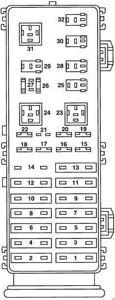
| Position | Rating [A] | Protected component / function |
|---|---|---|
| 1 | 40 | Junction block |
| 2 | 30 | Electronic engine-control power |
| 3 | 40 | Ignition |
| 4 | 30 | Power locks |
| 5 | 40 | Ignition |
| 6 | 30 | Power seats |
| 7 | 40 | Rear-window defrost |
| 8 | 30 | Thermo-electric pump |
| 9 | 40 | Cooling fan |
| 10 | 20 | Fuel pump |
| 11 | 40 | Blower motor |
| 12 | 20 | Semi-active suspension |
| 13 | 40 | ABS module |
| 14 | 20 | Radio |
| 15 | 15 | Daytime Running Lamps |
| 16 | 10 | Airbag |
| 17 | 20 | Radio |
| 18 | 30 | Headlamps |
| 19 | 15 | Horn |
| 20 | 15 | Parking lamps |
| 21 | – | Not used |
| 22 | 30 | Headlamps |
| 26 | 30 | Alternator |
| 27 | 10 | HEGO power |
| Relay | ||
| 23 | Relay | Blower-motor relay |
| 24 | Relay | Wiper relay |
| 25 | Relay | Wiper high/low relay |
| 28 | Relay | Washer-motor relay |
| 29 | Relay | Horn relay |
| 30 | Relay | Autolamp headlamp relay |
| 31 | Relay | Starter relay |
| 32 | Relay | Automatic-control relay |
Commonly checked fuses
- Cigarette lighter: cabin position 21 – 20 A.
- OBD / DLC connector: cabin position 25 – 10 A.
- Fuel pump: under-hood position 10 – 20 A, with fuel-pump relay 29 on the 1997-1999 layout.
- Front wiper: cabin position 17 – 30 A.
- Low beams: cabin positions 3 and 4 – 10 A each.
- ABS: under-hood positions 13 and 18 on the 1997-1999 layout.
FAQ – Mercury Sable 1996-1999 fuses
Why are there separate 1996 and 1997-1999 under-hood tables?
The power distribution box changed after 1996. The physical numbering and relay assignments are not identical.
Where is the cigarette-lighter fuse?
Cabin position 21 – 20 A.
Where is the diagnostic connector fuse?
Cabin position 25 – 10 A supplies the Data Link Connector.
Where is the fuel-pump fuse?
The under-hood fuel-pump circuit is position 10 – 20 A. On the 1997-1999 layout, the fuel-pump relay is position 29.