
The Audi 200 C3 (1989-1991) uses a combined engine-compartment fuse and relay carrier, with 29 numbered fuse positions and 11 main relay sockets. A further 17-position auxiliary relay carrier is installed beneath the driver’s dashboard. This electrical arrangement resembles the Audi 100 C3, but identical socket numbers do not always indicate identical functions, particularly in the radiator cooling system. This guide preserves unused slots, nominal fuse ratings from historical reference lists and equipment-dependent differences without assuming every position is occupied.
Where are the Audi 200 C3 fuse boxes?
Under the bonnet: With the ignition switched off, raise the bonnet and locate the main electrical box on the left side of the engine bay next to the base of the windscreen. Release the plastic cover catches and use the position diagram and lid legend. Fuses numbered 1-29 and relay sockets numbered 1-11 are housed in the main carrier. A nominal rating shown for an unused slot does not mean a fuse should be installed.
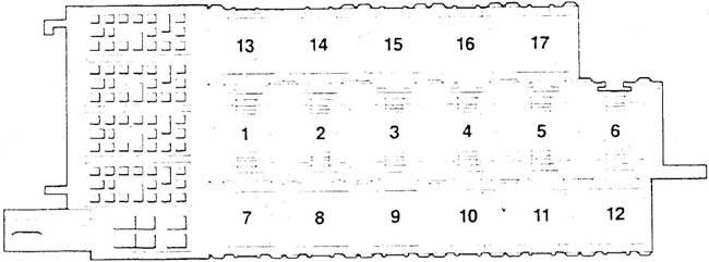
Driver-side dashboard: Open the driver’s door and remove the lower dashboard trim in the footwell. The separate auxiliary relay board is behind this trim, with positions 1-17. It contains ABS and heater control modules, electric-window circuitry and a resetting circuit breaker. Its position numbering is independent of the under-bonnet board.
Main fuse box – positions 1-29
The fuse list includes headlamps, engine injection, cooling, seats and accessories. Some early-market cars built before November 1988 omitted position 1, and some sockets have an unused designation despite a printed nominal rating. Match the as-built panel rather than fitting a fuse by assumption.
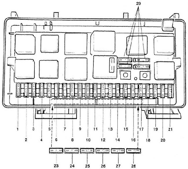
| Pozycja | Amperaż [A] | Chroniony obwód / funkcja |
|---|---|---|
| 1 | 15 | Front and rear fog lamps; on some vehicles built before November 1988 this slot was unoccupied |
| 2 | 15 | Hazard warning lamps |
| 3 | 25 | Horn and brake/stop lamps |
| 4 | 15 | Reading lights, boot and cabin lighting, cigarette lighter, illuminated vanity mirrors and trip computer |
| 5 | 30 | Unused on this installation; older source lists a nominal 30 A for the location |
| 6 | 5 | Right-hand side and parking lamps |
| 7 | 5 | Left-hand side and parking lamps |
| 8 | 10 | Right-hand high-beam headlamp |
| 9 | 10 | Left-hand high-beam headlamp |
| 10 | 10 | Right-hand dipped-beam headlamp |
| 11 | 10 | Left-hand dipped-beam headlamp |
| 12 | 15 | Instrument cluster, reversing lamps, cruise control and temperature switch |
| 13 | 15 | Fuel pump |
| 14 | 5 | Glovebox, engine compartment and licence-plate lighting |
| 15 | 25 | Front windscreen wipers |
| 16 | 30 | Rear window defogger and heated exterior mirrors |
| 17 | 30 | Heating and ventilation blower motor |
| 18 | 5 | Rear wiper, estate/Avant models only |
| 19 | 10 | Central locking; on some related Audi 100/100 quattro configurations the fuel injection controller |
| 20 | 30 | Heated seats and seat-position memory circuit |
| 21 | 25 | Unused on this installation; nominal 25 A in the older list |
| 22 | – | Unused position |
| 23 | 30 | Unused on this installation; nominal 30 A in the older list |
| 24 | 10 | Unused on this installation; nominal 10 A in the older list |
| 25 | 30 | Electrically adjustable seats with memory, including passenger seat |
| 26 | 5 | Auto-Check monitoring, electric mirror adjustment and driver seat memory |
| 27 | 10 | Ignition control circuit on Audi 100 / 100 quattro variants; verify fitment on the Audi 200 itself |
| 28 | 15 | Fuel injection controller, circuit II |
| 29 | – | Spare fuses kept in holder, not connected to an active circuit |
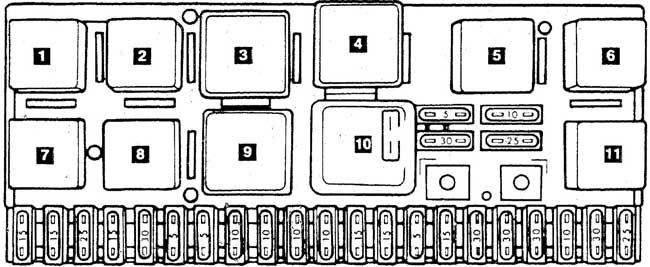
Under-bonnet main relays – positions 1-11
These relay sockets belong to the same engine-bay carrier but are shown on a separate diagram. The Audi 200 uses relay 3 for the first stage of cooling fan operation, whereas the same number can serve engine-off fan after-run on the related Audi 100. The fuel pump uses relay position 10.
| Pozycja | Amperaż [A] | Chroniony obwód / funkcja |
|---|---|---|
| 1 | – | Unused relay socket |
| 2 | – | Second-stage engine cooling fan |
| 3 | – | Audi 200: first-stage radiator cooling fan; related Audi 100: radiator fan after-run control |
| 4 | – | Unused relay socket |
| 5 | – | Load-reduction relay during engine cranking |
| 6 | – | Unused relay socket |
| 7 | – | Horn relay |
| 8 | – | Factory anti-theft alarm relay |
| 9 | – | Intermittent wiper and washer relay |
| 10 | – | Fuel pump relay |
| 11 | – | Air-conditioning relay |
Auxiliary relay board – positions 1-17
Under the dashboard, the auxiliary panel has modules for bulb monitoring, ABS, high-speed cooling fan operation, seat heating and electric-window control. Position 14 is a resetting circuit breaker, not a regular blade fuse; the two electric-window module sockets at 10 and 11 may form a combined assembly.
| Pozycja | Amperaż [A] | Chroniony obwód / funkcja |
|---|---|---|
| 1 | – | Unused relay position |
| 2 | – | Warning module for seat belt, parking lamps left on and radio |
| 3 | – | Courtesy lighting delay module |
| 4 | – | Unused relay position |
| 5 | – | Front lighting bulb-failure monitoring module |
| 6 | – | Unused relay position |
| 7 | – | Third-stage radiator cooling fan relay |
| 8 | – | ABS system relay |
| 9 | – | Intensive front windscreen washer relay |
| 10 | – | Electric window control module, first position |
| 11 | – | Electric window control module, second position |
| 12 | – | Rear wiper and washer relay, depending on body style |
| 13 | – | Unused relay position |
| 14 | – | Electric window resetting circuit breaker; not an ordinary blade fuse |
| 15 | – | Driver seat heating relay |
| 16 | – | Passenger seat heating relay |
| 17 | – | Unused relay position |
Where Audi 100 C3 and 200 C3 differ
The Audi 100 and Audi 200 C3 share the basic electrical panel architecture, but fitted turbo engines, automatic climate control, ABS, electric seat memory and market specifications affect fuse and relay occupation. In particular, relay 3 is not a reliable guide to cooling fan control without checking which model and year the drawing describes. Positions 5, 21, 23 and 24 are listed with nominal fuse values in older documents even where the corresponding circuits are unused on this arrangement.
Which fuses protect the lighter, wipers and fuel pump?
Cigarette lighter and interior lighting: Main fuse 4 (15 A) covers the lighter, reading lamps and interior lighting. Horn and brake lights: Fuse 3 (25 A) serves both circuits; the horn also has relay 7. Front wipers: Fuse 15 (25 A) protects the wiper supply and relay 9 operates intermittent wiping.
Fuel pump: Main fuse 13 (15 A) and relay 10 are the starting points for diagnosis if the pump does not receive power. Rear-window heating: Fuse 16 (30 A) serves the heated glass and exterior mirrors; fuse 17 (30 A) is the blower supply. Cooling: Check the first- and second-stage relays 3 and 2 together with auxiliary relay 7 for the third stage, as well as the motor and thermoswitch.
Audi 90 B3 from the same years
The smaller Audi 90 B3 (1986-1991) was sold during part of the same period and also uses a main and auxiliary relay carrier. Its fuse positions and cooling system details differ from those of the Audi 200 C3 and must be checked separately.
Technical reference: Audi 100/200 C3, “Fuse Panel Identification” 1989 and relay socket documentation for 1989-1991. Confirm the particular model, market and as-built fuse-box markings.