
Hyundai Trajet FO (2004-2008) uses a fuse box behind the driver’s side dashboard and a main electrical distribution box in the engine compartment. Diesel models can have another high-current block for glow plugs, fuel heating and supplementary cabin heating. This guide retains all 32 passenger-compartment fuse positions, 22 numbered under-bonnet positions, seven additional fusible links and five diesel-only protections. Equipment and circuit occupation vary with engine and country of sale.
Where are the Hyundai Trajet fuse boxes?
Inside the car: Switch the ignition off, open the driver’s door and find the fuse access flap low on the dashboard beside the steering column. Release the intended handle rather than forcing the plastic trim. The board contains 32 numbered fuse positions. Right-hand-drive models may have the panel in a mirrored location.
Under the bonnet: Locate the black plastic fuse and relay housing at the side of the engine compartment near the battery. Release its cover catches, lift the lid and use the legend printed inside to identify positions 1-22 and the larger power-distribution links. Auxiliary relays for the starter, horn, headlamps and air conditioning may be located separately depending on equipment.
Diesel models: Some Trajets have a separate high-current electrical box for the glow plugs, diesel fuel-filter heater and supplemental heating elements. Its layout is not shown in the two retained standard diagrams, so identify each position using the markings on the vehicle’s own auxiliary box.
Passenger compartment fuses – positions 1-32
The cabin panel protects the lighter, power outlets, airbag electronics, lighting, windscreen wipers, central locking and optional rear air conditioning. Individual equipment may be absent on a particular vehicle.

| Pozycja | Amperaż [A] | Chroniony obwód / funkcja |
|---|---|---|
| 1 | 10 | Immobiliser, instrument cluster, overhead console lamp, engine control module (ECM), mass air flow (MAF) sensor and engine oil level sensor |
| 2 | 10 | Instrument cluster |
| 3 | 10 | Hazard warning light switch |
| 4 | 15 | Supplemental Restraint System (SRS) airbag control module |
| 5 | 20 | Additional 12 V accessory power outlet |
| 6 | 10 | Radio, electrically adjustable exterior mirrors and power-folding mirrors |
| 7 | 15 | 12 V cigarette lighter |
| 8 | 10 | Seat belt tension reduction system |
| 9 | 10 | Air-conditioning control and power-folding mirrors |
| 10 | 10 | Air-conditioning control panel |
| 11 | 10 | Automatic light control, transmission control module (TCM), automatic gearbox signals, reversing lights and range switch |
| 12 | 10 | Climate control panel, audio unit and overhead console lamp |
| 13 | 10 | Interior lighting and instrument cluster |
| 14 | 15 | Central locking relay |
| 15 | 20 | Factory audio amplifier |
| 16 | 15 | Sunroof and overhead console lighting, depending on equipment |
| 17 | 15 | Immobiliser and electric fuel filler flap release |
| 18 | 10 | Rear fog lamp |
| 19 | 30 | Heated rear window relay and the circuit associated with fuse 9 |
| 20 | 10 | Jumper connector B, panel illumination, rear fog lamp and exterior lights |
| 21 | 10 | Climate control, sunroof and rain sensor, where fitted |
| 22 | 15 | Rear air conditioning, where fitted |
| 23 | 10 | Hazard warning relay and diagnostic connector |
| 24 | 15 | Brake pedal switch and stop light circuit |
| 25 | 20 | Front windscreen wipers, washers and rain sensor |
| 26 | 30 | Ignition coil supply, ABS, engine control relay and ECM |
| 27 | 10 | Alarm relay, cruise control, automatic gearbox range sensor, manual-transmission starting system, ECM and PCM |
| 28 | 10 | Headlamps, registration-plate lamps and additional exterior lighting |
| 29 | 10 | Brake lamp switch, cruise control, front wipers and fuel filter heater |
| 30 | 20 | Heated seats, if fitted |
| 31 | 10 | Air quality sensor (AQS), headlamp levelling and daytime running light control |
| 32 | 15 | Rear windscreen wiper and washer |
Main engine compartment – fuses 1-22 and high-current fusible links
High-current links are listed separately as FL1-FL7 for readability. Those FL labels are editorial identifiers for the seven additional links, not original factory fuse numbers. The names CONDENSER FAN, POWER WINDOW, IGNITION SWITCH, ABS, PASSENGER COMPARTMENT JUNCTION BLOCK and RADIATOR FAN are taken from the source layout. The original duplicated description for position 14 is not repeated.
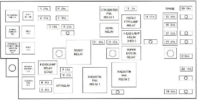
| Pozycja | Amperaż [A] | Chroniony obwód / funkcja |
|---|---|---|
| 1 | 20 | FUEL PUMP – Fuel pump relay feed |
| 2 | 15 | HEAD LAMP (LOW) – Dipped-beam headlamp relay |
| 3 | 10 | ABS – Anti-lock braking control unit |
| 4 | 10 | INJECTOR – Injectors, SMARTRA immobiliser and stop lamp circuits |
| 5 | 10 | A/C COMPRESSOR – Air-conditioning clutch relay |
| 6 | 20 | ATM – Automatic gearbox relay and transmission control module |
| 7 | 30 | MAIN – Main engine management relay |
| 8 | 20 | IGNITION COIL – Ignition coils and misfire sensor |
| 9 | 15 | OXYGEN SENSOR – Oxygen sensor |
| 10 | 15 | EGR – Fuel pump and glow-plug relays, camshaft/crankshaft sensors, EGR and EVAP purge solenoid |
| 11 | 10 | HORN – Horn relay |
| 12 | 15 | HEAD LAMP (HIGH) – Main-beam headlamp relay |
| 13 | 15 | DRL – Daytime running lamp control module and alarm siren |
| 14 | 15 | FRONT FOG LAMP – Front fog lamp relay |
| 15 | 30 | SPARE – Spare fuse, not connected to an active circuit |
| 16 | 20 | SPARE – Spare fuse, not connected to an active circuit |
| 17 | 15 | SPARE – Spare fuse, not connected to an active circuit |
| 18 | 10 | SPARE – Spare fuse, not connected to an active circuit |
| 19 | 30 | BLOWER – Interior blower motor relay |
| 20 | 30 | IGNITION SWITCH 1 – Ignition switch ACC and IG1 circuits |
| 21 | 30 | PASSENGER COMPARTMENT JUNCTION BLOCK 1 – Cabin junction board, including fuses 22-24 |
| 22 | 10 | ECM – Alternator, ECM and TCM |
| FL1 | 30 | CONDENSER FAN – Air-conditioning condenser fan relay No. 1 |
| FL2 | 30 | POWER WINDOW – Electric window relay and supply |
| FL3 | 30 | IGNITION SWITCH 2 – Ignition switch IG2 and START circuits and starter relay |
| FL4 | 30 | ABS 1 – ABS first main supply circuit |
| FL5 | 30 | ABS 2 – ABS second main supply circuit |
| FL6 | 50 | PASSENGER COMPARTMENT JUNCTION BLOCK 2 – Cabin junction board, jumper A, fuses 12-19 and tail lamp relay |
| FL7 | 40 | RADIATOR FAN – Radiator cooling fan relay |
Extra diesel-engine fusible links
These are high-current protections associated with diesel engines and optional supplementary heating. They are listed separately because the standard engine-bay diagram above does not show this diesel-only fuse carrier. Confirm the physical box and engine specification before diagnosing its circuits.
| Pozycja | Amperaż [A] | Chroniony obwód / funkcja |
|---|---|---|
| FILTER | 30 | Diesel fuel filter heater |
| GLOW | 80 | Diesel glow plugs |
| PTC1 | 60 | First auxiliary positive temperature coefficient (PTC) electric heater circuit |
| PTC2 | 60 | Second auxiliary PTC electric heater circuit |
| FFH | 20 | Fuel-fired auxiliary heater, where fitted |
Cigarette lighter, wipers, engine starting and cooling fans
12 V sockets: Dashboard fuse 7 (15 A) protects the cigarette lighter. A separate accessory outlet is connected to dashboard fuse 5 (20 A), so one outlet can fail while the other still works.
Wipers: Front windscreen wipers use dashboard fuse 25 (20 A); the rear wiper uses fuse 32 (15 A). If the windows do not operate, inspect the engine-bay POWER WINDOW link FL2 (30 A) and the related window controls.
Fuel supply and cooling: For a no-start condition, check the engine-bay FUEL PUMP fuse 1 (20 A), MAIN fuse 7 (30 A) and ignition supply, alongside the actual fuel pump relay and wiring. A dead radiator cooling fan can involve the RADIATOR FAN link FL7 (40 A), its relay or the motor. On a diesel vehicle with difficult cold starts, separately inspect the high-current glow-plug circuit.
Other family MPVs from the same period
Another Korean people carrier from the early 2000s is the Kia Carens II (2002-2006). Both are practical family vehicles of a similar era, although the electrical components and fuse assignments differ between models.
Technical basis: Hyundai Trajet FO 2004-2008 fuse and relay circuit listings, including the optional diesel supplementary box. Confirm the original lid legend, engine and equipment before replacing a fuse.