
The Audi 90 B3 (1986-1991) has a combined fuse and relay box near the base of the windscreen in the engine compartment and a separate auxiliary relay carrier beneath the driver’s dashboard. The main table preserves all 29 numbered fuse positions, including two alternative entries for fuse 21, and 11 main relay sockets I-XI. The auxiliary table has 18 more positions, including unoccupied locations and a resetting circuit breaker. Equipment such as ABS, Auto-Check, air conditioning, heated seats and power windows affects the installed circuits.
Where are the Audi 90 B3 fuse boxes?
Engine compartment: Switch off the ignition, raise the bonnet and find the fuse housing on the left side of the bulkhead near the lower edge of the windscreen. Release the lid fasteners and compare fuse positions 1-29 and relay sockets I-XI against the actual panel. Do not interchange relays in different sockets just because the units look similar, since their contacts and wiring can differ.
Passenger compartment auxiliary board: At the driver’s footwell, remove the lower dashboard trim to access the separate relay panel numbered 1-18. This board includes warning modules, seat heaters, power windows and the S43 circuit breaker. The physical panel numbering starts over and must not be confused with the main fuse positions under the bonnet.
Engine compartment – fuses 1-29 and main relays I-XI
The first table combines the main fuse locations and the relay sockets marked with Roman numerals. It retains all empty locations and factory device codes (J series). The two rows for fuse 21 describe alternative electrical installations; they are not two separate fuses intended to be fitted together.
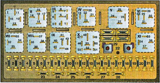
| Pozycja | Amperaż [A] | Chroniony obwód / funkcja |
|---|---|---|
| Fuses 1-29, including two alternative versions of position 21 | ||
| 1 | 15 | Front and rear fog lights |
| 2 | 15 | Hazard warning lamps and flasher |
| 3 | 25 | Horn and brake/stop lamps |
| 4 | 15 | Interior and reading lights, boot and glovebox lamps, cigarette lighter, radio, clock, trip computer, automatic climate control and alarm, according to equipment |
| 5 | 30 | Engine radiator cooling fan |
| 6 | 5 | Right-hand side, parking and marker lights |
| 7 | 5 | Left-hand side, parking and marker lights |
| 8 | 10 | Right-hand main beam and high-beam indicator |
| 9 | 10 | Left-hand main beam |
| 10 | 10 | Right-hand dipped beam |
| 11 | 10 | Left-hand dipped beam |
| 12 | 15 | Instrument panel, reversing lights, Auto-Check, cruise control, ABS, trip computer, differential locking, electronic thermoswitch and cooling fan control |
| 13 | 15 | Fuel pump and engine warm-up regulator |
| 14 | 5 | Glovebox, under-bonnet and number plate lamps |
| 15 | 25 | Front wipers, thermoswitch, cooling fan, indicators and A/C pressure switch |
| 16 | 30 | Rear window defogger and heated exterior mirrors |
| 17 | 30 | Cabin heater, ventilation and air-conditioning blower |
| 18 | 5 | Electric mirror adjustment; rear wiper on Coupe equipment variants |
| 19 | 10 | Central door locking and heated locks, according to specification |
| 20 | 30 | First-stage radiator cooling fan and fan after-run when engine stops |
| 21 | 10 | Diagnostic socket power supply – version of position 21 with 10 A |
| 21 | 25 | Rear cigarette lighter – alternative version of position 21 using 25 A, not an additional fuse fitted simultaneously |
| 22 | – | Unused position |
| 23 | 30 | Electric seats and memory control module |
| 24 | 10 | Engine control supply, circuit I |
| 25 | 30 | Heated front seats, where fitted |
| 26 | 5 | Daytime running lights for Canadian specification |
| 27 | 10 | Engine control supply, circuit I, from September 1987 |
| 28 | 15 | Engine management supply, circuit II |
| 29 | 15 | Spare fuse holder, not connected to an active circuit |
| Main relays I-XI | ||
| I | – | J5 relay for front fog lamps |
| II | – | Until model year 1990: J101 second-stage cooling fan; later arrangements may leave this socket empty |
| III | – | J138 radiator fan after-run control module |
| IV | – | Before 1990: unused; from the 1990 model year may carry J39 headlamp washer relay |
| V | – | J18 load reduction relay during engine cranking |
| VI | – | Earlier variants: J11 air-conditioning blower; from 1990: J101 high-speed cooling fan relay |
| VII | – | J4 horn relay |
| VIII | – | Automatic gearbox: J60 relay; manual gearbox: bridge between contacts 36 and 38 |
| IX | – | J31 intermittent front wiper and washer relay |
| X | – | J17 fuel pump relay |
| XI | – | J26 first-stage engine cooling fan relay |
Auxiliary relay panel – positions 1-18
The second panel includes ABS controller J156, the seat belt and light warning module J152, delayed courtesy lighting J140, the air-conditioning clutch controller J153 and optional seat heating. Socket 12 is the S43 resetting circuit breaker for power seats, windows and sunroof, not a conventional blade fuse.
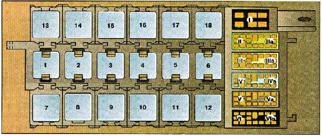
| Pozycja | Amperaż [A] | Chroniony obwód / funkcja |
|---|---|---|
| 1 | – | J156 ABS relay or control module |
| 2 | – | J152 seat belt, radio and parking-lamp warning module |
| 3 | – | J140 delayed cabin light switch-off module |
| 4 | – | J153 air-conditioning compressor clutch control |
| 5 | – | Unused position |
| 6 | – | Without Auto-Check: J114 oil pressure warning; with Auto-Check: J123 front lamp failure-monitoring module |
| 7 | – | Unused position |
| 8 | – | Unused position |
| 9 | – | Unused position |
| 10 | – | Unused position |
| 11 | – | Unused position |
| 12 | – | S43 resetting circuit breaker for memory seats, power windows and sunroof – not an ordinary blade fuse |
| 13 | – | J132 passenger seat heater controller |
| 14 | – | J131 driver seat heater controller |
| 15 | – | J139 sunroof and electric window control module, first position |
| 16 | – | J139 sunroof and electric window control module, second position |
| 17 | – | Electrical connector / distribution point for optional equipment |
| 18 | – | Unused position |
Why does fuse number 21 appear twice?
Some Audi 80/90 B3 circuit references describe fuse 21 as a 10 A diagnostic socket supply, while other market or equipment lists give a 25 A rear cigarette lighter at that same numbered position. These are alternative assignments, not interchangeable fuse ratings and not two simultaneous fuses. Confirm the correct application using the vehicle’s model-year wiring information and lid legend. Some 1988 and 1989-1991 vehicles are wired differently.
Main relay changes around model year 1990
Relay II served the second-stage radiator fan (J101) on earlier cars and can be unused in later versions. Position IV may be unused before 1990 and carry headlamp washer relay J39 from 1990. Position VI can change from air-conditioning blower relay J11 to high-speed cooling fan relay J101. At position VIII, an automatic transmission can have relay J60, whereas a manual gearbox can use a bridge between terminals 36 and 38. Check the model year and market before diagnosing these circuits.
Diagnosing the lighter, horn, wipers and fuel pump
Front cigarette lighter: Main fuse 4 (15 A) protects the lighter and various interior consumers; on a car with a rear lighter, use the correct variant of position 21. Front wipers: Fuse 15 (25 A) and relay IX (J31) supply the wipers and intermittent operation.
Horn and brake lamps: Fuse 3 (25 A) is associated with both circuits, together with horn relay VII (J4). Fuel pump: Fuse 13 (15 A) and relay X (J17) are important checks before condemning the pump. Rear-window demister: Fuse 16 (30 A) covers the rear glass and exterior mirrors, while fuse 17 (30 A) supplies the cabin blower. Cooling system relay assignment varies by model year.
Audi 90 B3 and the larger Audi 200 C3
For the same late-1980s period, the Audi 200 C3 (1989-1991) uses a different fuse layout and supplementary relay board. Even when some fuse positions have similar labels, the diagrams must not be used as interchangeable wiring references.
Technical reference: Audi 80/90 B3 “Electrical System – Wiring” documentation for 1986-1991, including S and J component designations. Check the relevant production-year and market-specific fuse panel.