
The Volvo 850 (1993-1997) combines a main under-bonnet fuse panel with a central relay distribution unit. Its 40 numbered fuse and circuit-breaker positions did not retain identical assignments throughout production: the greatest changes are at positions 4, 8, 10, 18 and 26 between 1993-1995 and 1996-1997. This guide preserves the known alternatives from original owner manuals and service information instead of treating higher and lower amperage values as interchangeable.
Where is the Volvo 850 fuse and relay box?
Main fuse panel: Switch the ignition off, open the bonnet and locate the central electrical unit under its plastic lid on the left side of the engine compartment. Release the lid clips and read the position and amperage legend on the inside of the cover. The 1-40 positions include two unused locations and three thermal circuit breakers.
Relay carriers: The under-bonnet relay section is associated with the same central electrical unit, while another relay panel is accessed near the left end of the dashboard on applicable models. The 101-108 and 201-215 designations are relay/module sockets, not fuse numbers. Some assemblies occupy two numbered slots, so avoid swapping just one half of a shared module.
Fuse and circuit-breaker positions 1-40
For slots 37, 39 and 40, “Circuit breaker” means a resetting thermal protective device. It is not a blade fuse and has no standard replaceable fuse rating in the source table. For positions with multiple numeric values, select the specification for the exact build year, destination market and equipment.
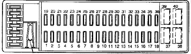
| Pozycja | Amperaż [A] | Chroniony obwód / funkcja |
|---|---|---|
| 1 | 15 | Fuel injection, ignition system and automatic gearbox |
| 2 | 15 | Fuel pump and anti-theft alarm system |
| 3 | 10 | Interior courtesy lighting and oil level sensor |
| 4 | – / 10 | 1993-1995 and US 1996-1997: unused; on some 1996 specifications: 10 A immobiliser / start inhibitor |
| 5 | 30 | Electronic climate control (ECC) blower, fourth speed |
| 6 | 25 | Central locking and alarm system |
| 7 | 15 | Audio system amplifier |
| 8 | 25 / – / 40 | 1993-1995: power antenna and trailer connector (25 A); US 1996-1997 manuals: unused; some 1996 configurations: immobiliser (40 A) |
| 9 | 30 | Anti-lock brakes (ABS) and traction control |
| 10 | – / 15 | 1993-1995: unused; 1996-1997: heated rear seat (15 A), where fitted |
| 11 | 30 | Heated rear window and exterior mirrors |
| 12 | 10 | Brake lamps |
| 13 | 15 | Hazard warning flashers, headlamp flash-to-pass and alarm |
| 14 | 30 | Second ABS and traction-control supply circuit |
| 15 | 10 | Audio, courtesy and boot lamps, glovebox, central locking, door lamps, belt reminder and, on some models, OBD diagnostics |
| 16 | 30 | Power antenna, trailer connector and accessory electrical circuits |
| 17 | 10 | Key-in-ignition warning and seat-belt reminder |
| 18 | 25 / 15 | 1993-1995: heated front seats and power mirrors (25 A); 1996-1997: front fog lamps (15 A) |
| 19 | 15 | Left-hand main-beam headlamp |
| 20 | 15 | Right-hand main-beam headlamp and high-beam warning light |
| 21 | 15 | Left-hand dipped-beam headlamp |
| 22 | 15 | Right-hand dipped-beam headlamp |
| 23 | 10 | Left-hand parking lamps and number-plate lighting |
| 24 | 10 | Right-hand parking lamps and bulb-failure warning |
| 25 | 10 | Rear fog lamp and warning light |
| 26 | – / 25 | 1993-1995: unused; 1996-1997: heated seats and mirror adjustment (25 A) |
| 27 | 15 | Reversing lamps and turn indicators |
| 28 | 10 | Cruise control, heated rear window, belt reminder, shift interlock, bulb warning and optional heated rear seat |
| 29 | 15 | ABS and traction control electronics |
| 30 | 10 | Cigarette lighter and 12 V power socket |
| 31 | 25 | ECC air conditioning, blower speeds 1-3 and compressor clutch |
| 32 | 10 | Radio and remote central locking |
| 33 | 15 | 1993-1995: power seats, OBD connector and estate rear wiper; 1996-1997: primarily the estate rear wiper and washer |
| 34 | 25 | Front windscreen wipers, washers, headlamp washers and horn |
| 35 | 10 | Instrument cluster illumination, sunroof and some traction-control functions |
| 36 | – | Unused position |
| 37 | Circuit breaker | Power windows and sunroof thermal circuit breaker, not a conventional blade fuse |
| 38 | – | Unused position |
| 39 | Circuit breaker | Driver’s electric seat thermal circuit breaker |
| 40 | Circuit breaker | Front passenger’s electric seat thermal circuit breaker |
Central electrical unit relay and module positions
Relay modules numbered 101-108 and 201-215 can provide fuel-pump supply, cooling and heating controls, headlamps, wipers, door locking and alarm operation. Assemblies 101-102, 104/108, 205-206 and 210-211 span multiple mounting positions.
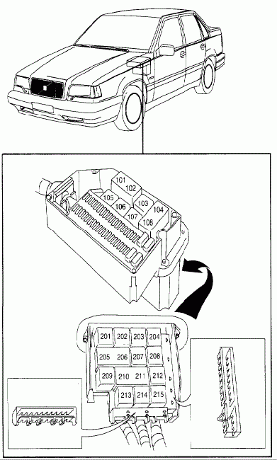
| Pozycja | Amperaż [A] | Chroniony obwód / funkcja |
|---|---|---|
| 101 | – | Cruise-control module, first position in combined assembly 101-102 |
| 102 | – | Cruise-control module, second position in combined assembly 101-102 |
| 103 | – | Fuel pump relay |
| 104 | – | Headlamp main relay and bulb-failure monitoring, first part of combined module 104/108 |
| 105 | – | Load-reduction relay for +X supply |
| 106 | – | Ignition-on +15 power relay |
| 107 | – | Second +X load-reduction relay |
| 108 | – | Second position of headlamp relay / bulb-checking assembly 104/108 |
| 201 | – | 1993-1995: oil level or bulb-monitoring module; some 1996 vehicles: front fog lamp relay |
| 202 | – | Central-locking deadlock relay |
| 203 | – | Front wiper intermittent operation relay |
| 204 | – | Estate rear-window wiper intermittent relay |
| 205 | – | Central locking and delayed interior-light module, first position of assembly 205-206 |
| 206 | – | Second position of central locking and courtesy lighting module 205-206 |
| 207 | – | Speed warning module; exhaust gas temperature sensor on some markets |
| 208 | – | Heated rear window and exterior mirror relay |
| 209 | – | Unused position |
| 210 | – | Factory alarm module relay, first position of assembly 210-211 |
| 211 | – | Factory alarm module relay, second position of assembly 210-211 |
| 212 | – | Seat-belt and ignition key warning relay |
| 213 | – | 1993-1995: automatic gearbox selector interlock; some 1996 versions: front fog relay or bridge |
| 214 | – | Heated rear seat relay |
| 215 | – | Unused position |
The 1993-1995 and 1996-1997 electrical differences
Fuse 18 protected heated front seats and mirrors at 25 A on many 1993-1995 cars, but was reassigned to 15 A front fog lamps on many 1996-1997 cars. Heated seats and mirrors are instead associated with fuse 26 (25 A) on later installations; earlier fuse 26 may be empty. The rear seat heater moves to fuse 10 (15 A) on some 1996-1997 variants, while that position is usually empty on older examples.
At fuse 4 and especially fuse 8, Volvo service diagrams and owner manuals from different markets do not agree on whether a slot is empty or protects the immobiliser. Fuse 8 may be the 25 A antenna and trailer circuit in 1993-1995, unoccupied in US 1996-1997 handbooks, or the 40 A immobiliser link on some 1996 layouts. Never substitute a 40 A fuse where the original installation specified 25 A or an empty slot. Five-cylinder petrol, turbo T-5, automatic transmission, ECC climate control, powered seat and alarm options also affect occupancy.
Which Volvo 850 fuse should you check?
12 V lighter: Fuse 30 (10 A) protects the lighter circuit. Fuel pump: Fuse 2 (15 A) and fuel pump relay 103 are relevant to a failed fuel-supply circuit. A repeated fuse failure indicates a wiring or component problem.
Rear window heating and mirrors: Fuse 11 (30 A) and relay 208 serve the demister circuits. Rear wiper on estate models: Fuse 33 (15 A) and relay 204 are associated with intermittent wiping. Power windows and seats: Positions 37, 39 and 40 use circuit breakers; inspect them and their electrical loads rather than attempting to fit normal fuse blades.
Volvo 850, S70 and V70
The Volvo S70 and first-generation V70 followed the 850 and inherited some of its engineering, but their fuse assignments are not identical. Much later Volvo V70 III / XC70 II (2007-2016) models use a substantially different electrical architecture; their fuse diagrams are listed separately.
Technical basis: Volvo 850 owner handbooks for 1995, 1996 and 1997 and Volvo “Fuses and Circuit Breakers” service information for 1993-1996. Check market, build year and fuse cover before replacement.