
Dacia Duster II HM/HJD (2022-2023) is the facelifted second-generation SUV, available with TCe petrol, Blue dCi diesel and factory ECO-G LPG powertrains, 2WD or optional 4×4. It has an interior fuse carrier and separate protected circuits in the engine compartment. The exact locations and fuse allocations differ by electrical equipment, engine and market.
The reference material for these years includes two different 49-position cabin fusebox layouts. One numbers cavities 1-49, while another is based on a physical cabin cover labelled 24313 8249 R and numbers positions F1-F49. Their cigarette lighter fuses differ, so match the actual fuse carrier and cover label instead of guessing from the first registration year.
Below are 126 preserved original entries across three complete tables: 49 in each cabin variant, plus 19 named engine fuse locations and 9 relays. Some allocations originate from supplementary technical diagrams rather than a universal factory-issued fuse table; entries lacking a firm assignment are identified instead of being invented. Dacia’s official HJD handbook confirms access to fuse flaps and the separate LPG isolation fuse, but does not provide one fixed amp rating for all these expanded lists.
Where are the Duster II fuse boxes?
Driver’s side: switch off ignition and electric accessories, move the driver’s seat back and locate the fuse protection flap beneath the left side of the dashboard. Dacia’s handbook identifies it as flap 1, released through notch 2. Carefully detach it and check the fuse-allocation label on the reverse; the fuse puller is also stored there.
Passenger glovebox option: on some variants a second accessible fuse carrier is behind flap 3, released through notch 4 inside or behind the passenger glovebox. Open the glovebox, unclip the designated flap and use its own fuse label. An empty-looking cavity must not be populated unless the vehicle manufacturer specifically assigns a protected circuit to it.
Engine compartment: manufacturer reference HJD identifies protected engine fuse units C and D around the main engine bay electrical distribution. Their access may require workshop procedures, especially for bolted high-current circuits. Stop the engine and park the wipers before opening the bonnet. The radiator fan can start unexpectedly and nearby components may be hot.
Cabin fusebox 1-49 – 2022 reference arrangement
This numbering arrangement is a secondary G2 technical reference. Its front 12 V socket is position 46 (15 A), radio position 47 (25 A), rear wiper position 25 (15 A) and front wipers position 44 (30 A). The positions with no verified consumer remain in the table as unconfirmed rather than being called universally vacant.
This reference should only be used when its drawing and physical socket arrangement correspond to the car; it is not proof that every model registered in 2022 or 2023 has the same panel.
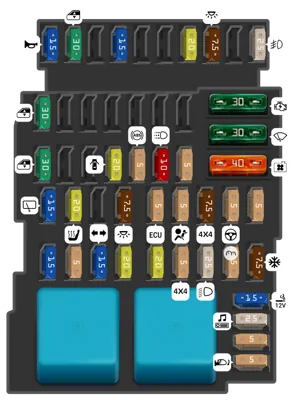
| Position | Amperage [A] | Protected circuit / function |
|---|---|---|
| 1 | 15 | Horn and audible warning signal |
| 2 | 30 | Electric power windows |
| 3 | Unconfirmed | No confirmed assignment for this 2022 reference position. This does not mean the socket is unoccupied in every vehicle. |
| 4 | 15 | Factory ECO-G LPG electrical supply where fitted |
| 5 | Unconfirmed | No confirmed assignment for this 2022 reference position. This does not mean the socket is unoccupied in every vehicle. |
| 6 | Unconfirmed | No confirmed assignment for this 2022 reference position. This does not mean the socket is unoccupied in every vehicle. |
| 7 | 20 | Energy management and keyless access electronics |
| 8 | 7.5 | Interior courtesy lighting |
| 9 | Unconfirmed | No confirmed assignment for this 2022 reference position. This does not mean the socket is unoccupied in every vehicle. |
| 10 | 25 | Front fog lamps, where fitted |
| 11 | 30 | Front electric window regulators |
| 12 | Unconfirmed | No confirmed assignment for this 2022 reference position. This does not mean the socket is unoccupied in every vehicle. |
| 13 | Unconfirmed | No confirmed assignment for this 2022 reference position. This does not mean the socket is unoccupied in every vehicle. |
| 14 | Unconfirmed | No confirmed assignment for this 2022 reference position. This does not mean the socket is unoccupied in every vehicle. |
| 15 | Unconfirmed | No confirmed assignment for this 2022 reference position. This does not mean the socket is unoccupied in every vehicle. |
| 16 | Unconfirmed | No confirmed assignment for this 2022 reference position. This does not mean the socket is unoccupied in every vehicle. |
| 17 | Unconfirmed | No confirmed assignment for this 2022 reference position. This does not mean the socket is unoccupied in every vehicle. |
| 18 | 30 | Rear electric windows |
| 19 | Unconfirmed | No confirmed assignment for this 2022 reference position. This does not mean the socket is unoccupied in every vehicle. |
| 20 | Unconfirmed | No confirmed assignment for this 2022 reference position. This does not mean the socket is unoccupied in every vehicle. |
| 21 | 20 | Central door locking |
| 22 | 5 | ABS/ESC electronic control system |
| 23 | 10 | Daytime running lamps |
| 24 | 5 | Rear power window child lock |
| 25 | 15 | Rear windscreen wiper |
| 26 | 20 | Heated front seats |
| 27 | Unconfirmed | No confirmed assignment for this 2022 reference position. This does not mean the socket is unoccupied in every vehicle. |
| 28 | 7.5 | Cabin lighting |
| 29 | 5 | Engine management ECU |
| 30 | 5 | SRS airbag control unit |
| 31 | 7.5 | Four-wheel-drive controller |
| 32 | 5 | Electric power steering controller |
| 33 | 5 | Seatbelt pretensioners and belt reminder |
| 34 | 15 | Cabin body electrical controller |
| 35 | 5 | Second interior electrical supply |
| 36 | 15 | Direction indicators and hazard warning lights |
| 37 | 20 | Factory trailer electrical circuits |
| 38 | 20 | Immobiliser and hands-free entry |
| 39 | 5 | Second 4WD controller feed |
| 40 | 25 | Headlight main supply |
| 41 | 5 | Instrument cluster |
| 42 | 7.5 | Climate-control controller |
| 43 | 30 | Starter motor circuit |
| 44 | 30 | Front windscreen wiper motor |
| 45 | 40 | Engine radiator cooling fan motor |
| 46 | 15 | Front cigarette lighter and 12 V accessory outlet |
| 47 | 25 | Radio and factory multimedia |
| 48 | 5 | Heater and cabin ventilation control electronics |
| 49 | 5 | Electrically adjustable exterior mirrors |
Cabin fusebox F1-F49 – label 24313 8249 R
The other diagram is reconstructed from a fuse cover marked 24313 8249 R. It places the front cigarette lighter at F36 (15 A), front wiper at F34 (30 A), rear wiper at F15 (15 A) and horn at F40 (15 A). The F37 radio and climate supply can be rated 15 A or 25 A depending on vehicle configuration.
The source schematic is an HTML grid with enlarged labels, retained rather than reduced to a small raster image. All 49 slots are reproduced in the table immediately below, including positions with uncertain functions. Confirm the actual sticker before installing a fuse.
| Position | Amperage [A] | Protected circuit / function |
|---|---|---|
| F1 | 30 | Front electric window regulators |
| F2 | 10 | The function is not established by this particular fuse-label reference; verify the actual fitted fuseboard. |
| F3 | 10 | The function is not established by this particular fuse-label reference; verify the actual fitted fuseboard. |
| F4 | 10 | The function is not established by this particular fuse-label reference; verify the actual fitted fuseboard. |
| F5 | 10 | The function is not established by this particular fuse-label reference; verify the actual fitted fuseboard. |
| F6 | 5 | The function is not established by this particular fuse-label reference; verify the actual fitted fuseboard. |
| F7 | 5 | The function is not established by this particular fuse-label reference; verify the actual fitted fuseboard. |
| F8 | 30 | Rear electric windows |
| F9 | 7.5 | The function is not established by this particular fuse-label reference; verify the actual fitted fuseboard. |
| F10 | 20 | The function is not established by this particular fuse-label reference; verify the actual fitted fuseboard. |
| F11 | 20 | Central door locking and automatic door lock |
| F12 | 5 | ABS/ESC, clutch and brake signals, engine immobiliser |
| F13 | 10 | Interior, luggage compartment and glovebox lighting |
| F14 | 5 | Automatic light sensor and electric rear window child lock |
| F15 | 15 | Rear wiper motor and screenwash pump |
| F16 | 20 | Infotainment and optional heated seats |
| F17 | 10 | The function is not established by this particular fuse-label reference; verify the actual fitted fuseboard. |
| F18 | 7.5 | Power distribution, hands-free access and selected lighting |
| F19 | 5 | Engine injection controls, instrument cluster and cabin module |
| F20 | 5 | SRS airbags controller |
| F21 | 7.5 | 4WD transmission or automatic gearbox control |
| F22 | 5 | Electric power steering electronics |
| F23 | 5 | Seatbelt warning, parking assist, cruise control and rear window heater electronics |
| F24 | 15 | May be equipped but its circuit function is not confirmed |
| F25 | 5 | May be equipped but its circuit function is not confirmed |
| F26 | 15 | Turn signal and hazard warning lights |
| F27 | 20 | Factory towing module |
| F28 | 20 | Hands-free keyless access ECU |
| F29 | 25 | The function is not established by this particular fuse-label reference; verify the actual fitted fuseboard. |
| F30 | 25 | Left main beam, right dipped beam, left daytime running lamp and side/position lights |
| F31 | 5 | Instrument cluster |
| F32 | 7.5 | Radio, A/C panel, ventilation controls and rear accessory socket |
| F33 | 30 | Starter motor circuit |
| F34 | 30 | Front windscreen wipers |
| F35 | 40 | Heater/air-conditioning blower motor |
| F36 | 15 | Front cigarette lighter and 12 V socket |
| F37 | 15 / 25 | Radio and A/C feeds; 15 or 25 A according to installed version, including some 1.3 TCe engines |
| F38 | 5 | Electrically heated exterior mirrors |
| F39 | 5 | Electric exterior mirror adjustment |
| F40 | 15 | Horn and factory anti-theft alarm controller |
| F41 | 25 | Front electric window motors |
| F42 | 5 | 4WD or automatic transmission controller |
| F43 | 15 | Factory LPG preparation circuit, sometimes populated without LPG |
| F44 | 15 | Rear 12 V accessory outlet |
| F45 | Not stated | Function and rating not established for this exact label |
| F46 | 20 | The function is not established by this particular fuse-label reference; verify the actual fitted fuseboard. |
| F47 | 7.5 | Energy management and hands-free access; may be unpopulated |
| F48 | 25 | The function is not established by this particular fuse-label reference; verify the actual fitted fuseboard. |
| F49 | 25 | Right main beam, left dipped beam, right daytime running lamp, fog and position lamps |
Engine fusebox – positions 1-18, 21 and relays R1-R9
This engine reference covers fuse slots 1-18 and 21, along with nine separate relay entries. There are no independently documented slots 19 or 20 in the source configuration, so they have not been invented. Functions include ABS/ESC, radiator fan, engine ECU, starting, air-conditioning and optional heated front windscreen.
For example position 4 is given as 25 A or 40 A for stability control in different versions, while position 12 (30 A) serves the starter. Positions marked as spare refer to stored or optional protection rather than permission to substitute an incorrect fuse.
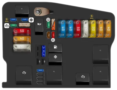
| Position | Amperage [A] | Protected circuit / function |
|---|---|---|
| 1 | 10 | Front fog lamps |
| 2 | 7.5 | Vehicle electronic control module |
| 3 | 30 | Rear screen and exterior mirror heating |
| 4 | 25 / 40 | Electronic stability control ESC/ESP: 25 or 40 A according to equipped power distribution |
| 5 | 60 | Main 60 A cabin circuits P11, P24-P27, P34, P39 and P41 |
| 6 | 60 | Ignition supply, cabin P28, P31, P38, P43, P46 and P47 |
| 7 | 50 | Second ABS/ESC main supply |
| 8 | 80 | Luggage compartment socket main feed in a specified vehicle variant; confirm fitted circuit |
| 9 | 20 | Spare fuse position, not an active consumer |
| 10 | 40 | Heated front windscreen stage 1 |
| 11 | 40 | Heated front windscreen stage 2 |
| 12 | 30 | Starter motor feed |
| 13 | 15 | Spare fuse position |
| 14 | 25 | Engine ECU electronic management feed |
| 15 | 15 | Air conditioning compressor clutch and relay |
| 16 | 50 | Engine cooling fan motor |
| 17 | 40 | Automatic transmission controller, if fitted |
| 18 | 80 | Electric power steering pump/controller main feed |
| 21 | 15 | Oxygen sensors, EVAP purge valve, camshaft sensor and variable timing solenoid |
| R1 | – | R1: horn relay |
| R2 | – | R2: factory alarm siren relay |
| R3 | – | R3: first starter relay |
| R4 | – | R4: engine management ECU main relay |
| R5 | – | R5: A/C compressor relay |
| R6 | – | R6: fuel pump relay |
| R7 | – | R7: heated windscreen stage 2 or cooling fan relay, equipment dependent |
| R8 | – | R8: heated windscreen stage 1 relay |
| R9 | – | R9: second starter relay |
ECO-G LPG fuse in engine module C
The official Dacia Duster II HJD manual shows a separate LPG shut-off fuse labelled 6 in engine compartment module C. It may interrupt the LPG circuit alone or both LPG and petrol circuits, depending on version. This callout must not be confused with fuse number 6, 60 A in the general engine table, which refers to a different electrical distribution layout. An LPG-related cabin fuse may also be fitted depending on the ECO-G system.
When the vehicle stops switching to gas, first check the 12 V battery, approved LPG fuse location and relevant diagnostic fault codes. Do not open pressurised LPG lines or bypass the shut-off protection.
2022 versus 2023, TCe, Blue dCi, ECO-G and 4WD differences
The Duster II facelift began in 2021. Different production periods can use different cabin fuse labels despite similar dashboard appearance. TCe petrol engines, Blue dCi diesel and ECO-G LPG also differ in injection and fuel supply electronics; 4×4, hands-free entry, heated seats, towbar electrics and automatic gearbox affect occupied positions.
The 24313 8249 R label has been seen on more than one production period, so it is not an exclusive 2022 or 2023 identifier. The fusebox cover, exact engine and VIN-specific wiring always take priority over the year-based heading.
Common Duster II electrical problems
Front 12 V socket does not work: inspect cabin 46 (15 A) only if your panel matches the 1-49 drawing, or F36 (15 A) if the cover is 24313 8249 R. A charger can short the socket contacts, causing repeated failures.
Rear wiper fails: the first panel uses 25 (15 A), the second F15 (15 A). For front wipers check 44 (30 A) or F34 (30 A). Wiper motors and broken wiring through the tailgate hinge can also cause these symptoms.
Central locking stops responding: cabin reference 1 uses 21 (20 A), while the cover-labelled reference uses F11 (20 A). If one door alone fails, examine the actuator and door-jamb wiring.
Cabin blower does not run: on the F1-F49 cover layout inspect F35 (40 A). The alternate 1-49 chart lists 48 (5 A) for the blower’s electronic control, not the same high-current motor feed. Fan-speed regulator and connector problems can also cause failure.
4WD or ECO-G fault: use the correct variant’s electrical supply diagram and read engine/4WD control-unit fault codes. Do not increase a fuse rating if it blows again.
Other Dacia fusebox diagrams
The previous Dacia Duster I (2010-2016) uses a different installation and is not a substitute for an HJD diagram. The Dacia Sandero II (2012-2020) and Dacia Sandero I (2008-2012) provide other brand-related references, but their fuses are numbered differently.
Manufacturer source: Dacia Duster II HM/HJD owner manual NU 1271-13 (English), “Practical advice – Fuses”, pages 285-287. This manual confirms cabin flap access, engine modules C/D and separate ECO-G LPG fuse number 6. The complete 49-position cabin lists and engine relay descriptions also use the cited Polish source article’s secondary reference material, which should be verified for the individual car.
Featured vehicle photograph: ROCostiTheBunnyCZ, 2021 facelifted Dacia Duster II, Wikimedia Commons, CC BY-SA 4.0, unmodified. Attribution and licence are preserved in WordPress media metadata.