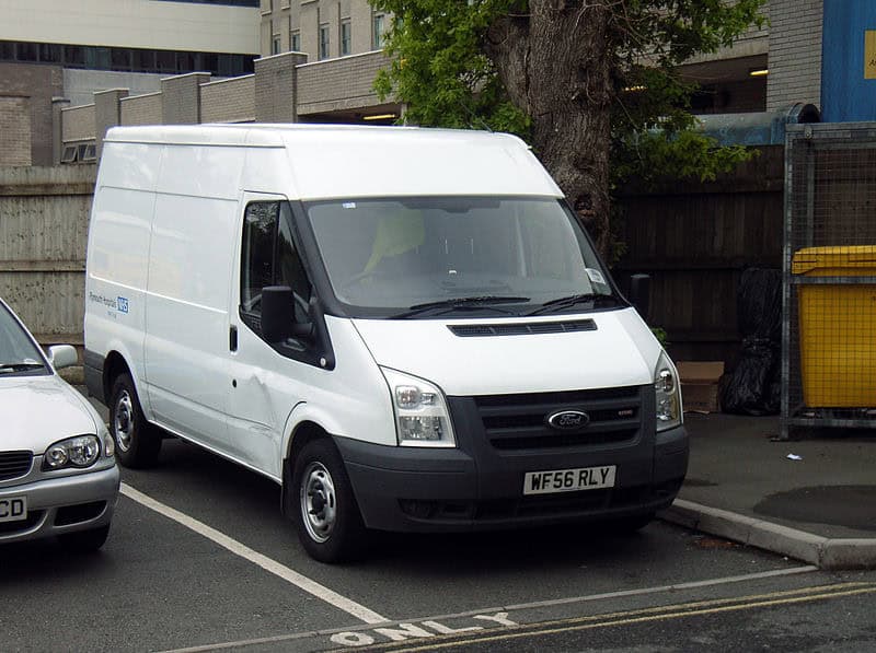
The European Ford Transit Mk7 from 2006 uses several separate fuse and relay locations rather than one central panel. Depending on equipment and production period, the electrical system includes a high-current pre-fuse box, an engine junction box, a standard relay box, a passenger-compartment junction box and two auxiliary fuses.
The tables below retain every position from the current source article, including unused positions and equipment-specific alternatives. Where the same fuse number has two configurations, both rows are shown separately rather than merged.
High-current pre-fuse box
The pre-fuse box carries the main high-current feeds for the starter, alternator, heated windshield, junction boxes and customer connection points. High-current fuses should be serviced with the battery disconnected.

| Fuse | Rating [A] | Color | Protected component / function |
|---|---|---|---|
| 1 | 350 | gray | Starter motor and alternator |
| 2 | 60 | yellow | Passenger junction box power supply – start-relevant / KL15 supply for Start-Stop variants |
| 3 | 100 | blue | Engine junction box power supply – non-start-relevant |
| 4 | 40 | green | Heated windshield – right-hand side |
| 5 | 100 | blue | Standard relay box power supply – non-start-relevant |
| 6 | 40 | green | Heated windshield – left-hand side |
| 7 | 60 | yellow | Passenger-compartment junction box power supply – non-start-relevant |
| 8 | 60 | yellow | Customer connection point |
| 9 | 60 | yellow | Customer connection point |
| 10 | 60 | yellow | Customer connection point |
| Relay | Circuits switched |
|---|---|
| R1 | Battery disconnect switch |
Engine junction box

| Fuse | Rating [A] | Color | Protected component / function |
|---|---|---|---|
| 11 | 60 | yellow | Engine cooling fan |
| 12 | 30 | pink | Trailer tow and trailer-tow module supply (KL30) |
| 13 | 40 | green | ABS and ESP pump |
| 14 | – | – | Not used |
| 15 | 60 | yellow | Glow plugs |
| 16 | 60 | yellow | Ignition relay (KL15 #3) |
| 17 | 30 | pink | Starter enable |
| 18 | 40 | green | Ignition feed (KL15) to passenger junction box – vehicles without Start-Stop |
| 18 | – | – | Not used – vehicles with Start-Stop |
| 19 | – | – | Not used |
| 20 | 10 | red | ABS, ESP, steering-angle sensor, yaw-sensor supply (KL30) |
| 21 | 25 | clear | ABS and ESP valves and control unit |
| 22 | – | – | Not used |
| 23 | – | – | Not used |
| 24 | 5 | tan | Fuel pump – without fuel-fired heater |
| 24 | 20 | yellow | Fuel pump – with fuel-fired heater |
| 25 | – | – | Not used |
| 26 | 15 | blue | PCM power supply |
| 27 | 5 | tan | Fuel pump – with fuel-fired heater |
| 28 | 5 | tan | T-MAF sensor |
| 29 | 5 | tan | Auxiliary-heater glow-plug monitoring |
| 30 | 7.5 | Fuel-vapor purge / speed-control valve | |
| 31 | 15 | blue | VAP/UEGO pump |
| 32 | 15 | yellow | Injector glow plug |
| 33 | 10 | red | Reversing lamps |
| 34 | 20 | yellow | Trailer KL15 supply |
| 35 | – | – | Not used |
| 36 | 10 | red | Air-conditioning clutch |
| 37 | – | – | Not used |
Some assignments depend on equipment and later production changes. Fuse 18 is shown separately for vehicles with and without Start-Stop, and fuse 24 has two ratings depending on the fuel-fired heater configuration.
| Relay | Circuits switched |
|---|---|
| R2 | Glow plugs |
| R3 | Trailer tow (KL15) |
| R4 | Starter enable |
| R5 | Power feed (KL15 #4) |
| R6 | Power feed (KL15 #3) |
| R7 | Fuel pump |
| R8 | Injector glow plug |
| R9 | Not used |
| R10 | Air-conditioning clutch solenoid |
Standard relay box

| Fuse | Rating [A] | Color | Protected component / function |
|---|---|---|---|
| 38 | 20 | yellow | Rear-window wiper |
| 39 | 10 | red | Front and rear air-conditioning controls |
| 40 | 5 | tan | Not used |
| 41 | 5 | tan | Tachograph |
| 42 | 5 | tan | Headlamp leveling, main lighting switch (KL15) |
| 43 | 20 | yellow | Heated front seats |
| 44 | 20 | yellow | Horn |
| 45 | 20 | yellow | Front auxiliary power socket |
| 46 | 10 | red | Heated exterior mirrors – with Category 1 alarm |
| 47 | 20 | yellow | Cigarette lighter |
| 48 | 5 | tan | Relay-coil supply, power mirrors |
| 49 | 20 | yellow | Rear auxiliary power socket |
| 50 | 10 | red | Left high beam |
| 51 | 10 | red | Right high beam |
| 52 | 10 | red | Left low beam |
| 53 | 10 | red | Right low beam |
| 54 | 30 | pink | Common supply for low/high beam, daytime running lamps, tachograph and fuel-fired auxiliary-heater blower |
| 55 | 40 | green | Heater blower motor |
| 56 | 20 | yellow | Power windows |
| 57 | 30 | pink | Rear heater blower motor |
| 58 | 30 | pink | Windshield wiper motor |
| 59 | 30 | pink | Heated rear window, heated exterior mirrors |
| 60 | – | – | Not used |
| 61 | 60 | yellow | Ignition relay (KL15 #1) |
| 62 | 60 | yellow | Ignition relay (KL15 #2) |
| Relay | Circuits switched |
|---|---|
| R11 | Low beam |
| R12 | Heated exterior mirrors with Category 1 alarm; power socket without Category 1 alarm |
| R13 | High beam |
| R14 | Horn |
| R15 | Daytime running lamps |
| R16 | Programmable fuel-fired heater |
| R17 | Heated rear-door windows and heated mirrors; or left rear-door heated window with Category 1 alarm |
| R18 | Right rear-door heated window – with Category 1 alarm |
| R19 | Power feed (KL15 #2) |
| R20 | Passenger junction box KL15 – Start-Stop only |
| R21 | Power feed (KL15 #1) |
| R22 | Heated windshield – right-hand side |
| R23 | Windshield wiper high/low speed |
| R24 | Rear-window wiper |
| R25 | Windshield wiper on/off |
| R26 | Heated windshield – left-hand side |
Passenger-compartment junction box

| Fuse | Rating [A] | Color | Protected component / function |
|---|---|---|---|
| 63 | 5 | tan | Rear parking aid, rain sensor |
| 64 | 2 | gray | Accelerator pedal position sensor |
| 65 | 15 | blue | Stop-lamp switch |
| 66 | 5 | tan | Instrument cluster, PATS supply, tachograph, instrument-panel switch illumination |
| 67 | 15 | blue | Washer pump |
| 68 | 10 | red | Supplemental restraint system control module |
| 69 | 20 | yellow | Exterior lighting switch (KL15) |
| 70 | 20 | yellow | Battery-backed alarm sounder |
| 71 | 5 | tan | Exterior lighting switch (KL30) |
| 72 | 10 | red | Battery-saver supply, OBD-II (KL30) |
| 73 | 15 | blue | Radio, navigation and telephone supply |
| 74 | 5 | tan | Instrument cluster, fuel-fired auxiliary-heater timer relay, keyless central-locking supply, interior-motion sensor (KL30) |
| 75 | 7.5 | brown | Right-hand position lamps |
| 76 | 7.5 | brown | Left-hand position lamps |
| 77 | 5 | tan | Ignition-switch supply, battery-disconnect switch coil supply |
| 78 | 15 | blue | Central locking |
| 79 | 7.5 | brown | License-plate lamp, side marker lamps |
| 80 | 15 | blue | Front fog lamps |
| 81 | 10 | red | Rear fog lamps |
| 82 | 3 | violet | Ignition supply to audio system and instrument cluster |
Auxiliary fuses
| Fuse | Rating [A] | Color | Protected component / function | Location |
|---|---|---|---|---|
| 83 | 10 | red | Trailer-tow module | Left-hand footwell |
| 84 | 7.5 | brown | DPF glow-plug control | Below the engine-compartment junction box |
FAQ – Ford Transit Mk7 fuses
Where is the main high-current fuse box?
The pre-fuse box is associated with the battery/main power distribution and contains the very high-current feeds, including the 350 A starter/alternator fuse.
Which fuses protect the heated windshield?
In the pre-fuse box, fuse 4 – 40 A protects the right-hand side and fuse 6 – 40 A the left-hand side. The standard relay box also uses R22 and R26 for the two windshield halves.
Where is the OBD-II supply?
Passenger-compartment fuse 72 – 10 A includes the OBD-II KL30 supply and the battery-saver circuit.
Which fuse supplies the radio?
Passenger-compartment fuse 73 – 15 A supplies the radio, navigation and telephone systems.
Why are there two entries for fuse 18?
The table covers different equipment configurations. The 40 A KL15 feed applies to vehicles without Start-Stop, while the same position is listed as unused on Start-Stop-equipped vehicles in the source configuration.
Why are there two entries for fuse 24?
The fuel-pump circuit differs according to whether a fuel-fired auxiliary heater is installed, so both factory-source variants are retained separately.
Can I replace high-current fuses myself?
Ford warns that the battery should be disconnected before servicing high-current fuses and recommends that high-current fuse and relay work be carried out by properly trained technicians.