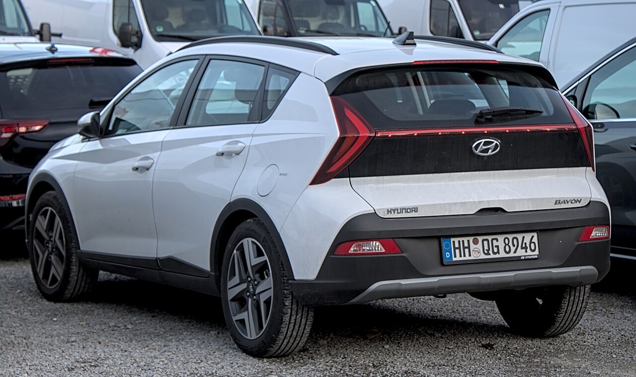
The Hyundai Bayon (introduced in 2021) has two main fuse panels: one behind the driver’s lower dashboard trim and one in the engine compartment. The diagrams and tables below refer to the 2022 model, including selected manual, DCT and 48 V mild-hybrid configurations. They cover 38 cabin positions (including the OBD connector), 41 engine-compartment fuse entries and 12 engine-bay relays.
Fuse allocation can differ between the 1.0 T-GDi and 1.2 MPI engines, G3LE/G4LC variants, 48 V mild-hybrid equipment and transmission systems. Not every labelled position is necessarily fitted on your vehicle. Match the cover label and rating on the actual fuse panel before replacement.
Where are the Hyundai Bayon fuse boxes?
Inside the cabin: behind an access panel at the lower left of the dashboard near the driver’s knee on left-hand-drive cars. Turn off the ignition, remove or open the panel gently and inspect its inside label. Right-hand-drive layouts can differ.
In the engine compartment: inside the lidded box near the 12 V battery. Release the retaining clips after switching the ignition off, identify the labelled slot and close the lid firmly to prevent moisture ingress.
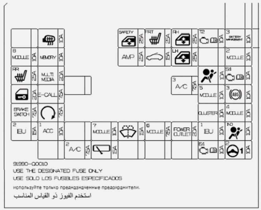
Hyundai Bayon 2022 – passenger compartment fuse panel
The cabin panel supplies the power socket, infotainment, windows, lighting, locks, air conditioning, washers and rear wipers. The last table entry is the OBD-II diagnostic connector, not a replaceable fuse, and therefore has no amperage rating.
| Position | Amperage [A] | Protected circuit / function |
|---|---|---|
| 2 | 10 | HEATED MIRROR – heated door mirrors |
| 3 | 25 | SAFETY P/WINDOW – driver’s power window safety circuit |
| 4 | 25 | FRONT SEAT WARMER – heated front seats |
| 5 | 25 | P/WINDOW RH – right-side power windows |
| 6 | 10 | TCU2 – transmission and clutch control module |
| 7 | 10 | BATTERY MANAGEMENT3 – 48 V mild hybrid battery management controller |
| 8 | 10 | MODULE 8 – diagnostic connector and central locking |
| 9 | 10 | MEMORY – stored settings and equipment controller supply |
| 10 | 25 | AMP – audio amplifier |
| 11 | 15 | SUNROOF – powered sunroof |
| 12 | 25 | P/WINDOW LH – left-side power windows |
| 14 | 10 | MODULE 2 – Sport mode and brake-light controls |
| 15 | 25 | REAR SEAT WARMER – heated rear seats |
| 16 | 20 | MULTI MEDIA – radio, display and navigation system |
| 17 | 10 | AIR BAG – SRS airbag control module |
| 18 | 10 | SENSOR4 – engine control components for G3LE/G4LC |
| 20 | 7.5 | A/C 3 – blower and HVAC control |
| 21 | 20 | DOOR LOCK – central locking and tailgate release |
| 22 | 7.5 | E-CALL – emergency calling module |
| 23 | 10 | MODULE 5 – audio, heating, charging and mirror control equipment |
| 24 | 10 | ABS 3 – ABS/ESC cabin control circuit |
| 25 | 7.5 | BRAKE SWITCH – brake-light switch |
| 26 | 7.5 | START – starting module and Integrated Body Control Unit (IBU) |
| 27 | 10 | CLUSTER – instrument cluster |
| 28 | 10 | MODULE 4 – driver assistance systems and camera |
| 29 | 15 | IBU 2 – Integrated Body Control Unit 2 |
| 30 | 10 | ACC 1 – accessories, radio and USB power supply |
| 32 | 10 | MODULE 7 – seat heating and parking assistance modules |
| 33 | 15 | WASHER – windscreen washers |
| 34 | 7.5 | MODULE 6 – body controller supply |
| 35 | 20 | POWER OUTLET – cigarette lighter / 12 V accessory socket |
| 36 | 10 | IBU 1 – Integrated Body Control Unit 1 |
| 37 | 10 | AIR BAG IND – SRS warning indicators |
| 39 | 7.5 | A/C 2 – HVAC controls and relays |
| 40 | 15 | WIPER RR – rear window wiper |
| 44 | 10 | ECU 4 – engine control module ECM/PCM |
| 45 | 10 | MDPS 2 – electric power steering |
| OBD | – | OBD-II diagnostic connector, not a fuse |
The POWER OUTLET at cabin position 35 is rated at 20 A. MULTI MEDIA at position 16 is 20 A; WASHER at position 33 is 15 A; WIPER RR at position 40 is 15 A.
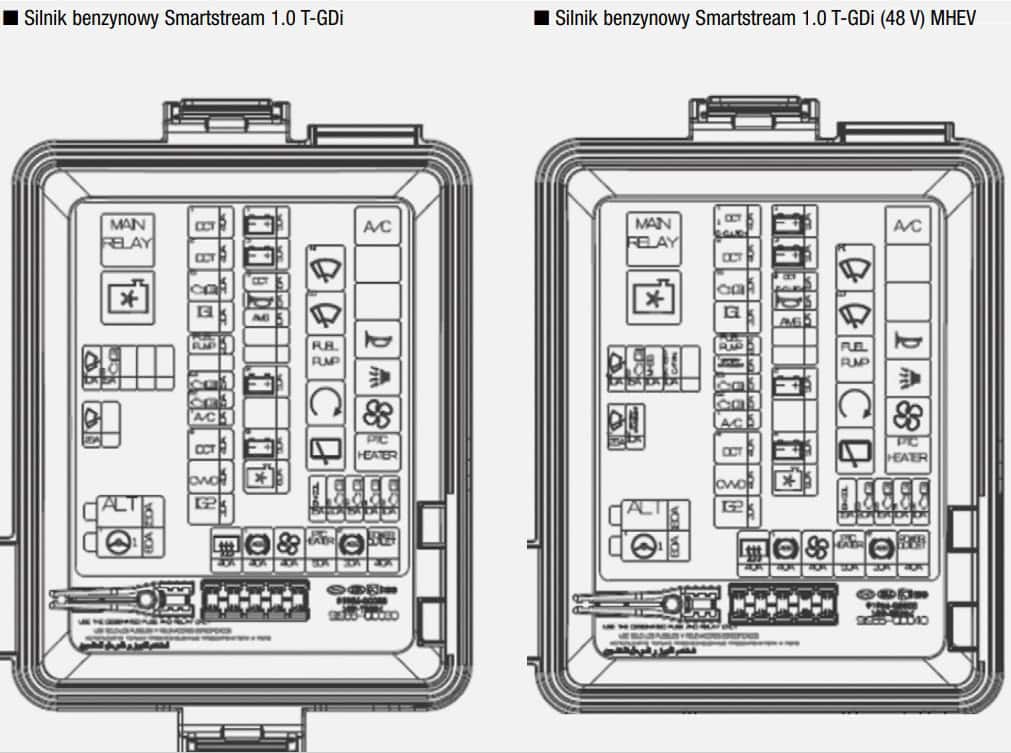
Hyundai Bayon 2022 – engine compartment fuses
This box protects main alternator feeds, the steering assistance, engine electronics, starter, ABS/ESC, cooling fan, fuel pump, heated rear window and windscreen wipers. The same physical position may be specified differently for cars with a DCT transmission or an electronically controlled clutch.
| Position | Amperage [A] | Protected circuit / function |
|---|---|---|
| 1 | 180 | ALT – alternator and main electrical supply protection |
| 2 | 80 | MDPS – electric power steering |
| 3 | 40 | DCT1 – dual-clutch transmission controller, first circuit; DCT-equipped cars only |
| 3 | 40 | E-CLUTCH1 – electronically controlled clutch module, first circuit; electronic-clutch cars only |
| 4 | 40 | DCT2 – dual-clutch transmission controller, second circuit |
| 5 | 30 | ECU1 – main engine control relay supply |
| 6 | 30 | IG1 – ignition-switched power supply |
| 7 | 20 | FUEL PUMP – fuel pump supply |
| 8 | 15 | BATTERY MGMT1 – battery management controller |
| 9 | 15 | ECU3 – engine controller and clutch pedal sensor |
| 10 | 15 | ECU2 – engine control module |
| 11 | 10 | A/CON 1 – air-conditioning relay |
| 12 | 40 | DCT4 – DCT gearbox actuator |
| 13 | 40 | CVVD – continuously variable valve duration actuator |
| 14 | 30 | IG2 – starting and ignition supply |
| 15 | 50 | BATT1 – cabin power distribution module feed 1 |
| 16 | 50 | BATT3 – cabin power distribution module feed 3 |
| 17 | 15 | DCT3 – DCT controller third circuit; DCT-equipped cars only |
| 17 | 15 | E-CLUTCH2 – electronically controlled clutch second circuit; electronic-clutch cars only |
| 18 | 15 | HORN – horn and horn relay |
| 19 | 10 | AMS – 12 V battery sensor |
| 22 | 50 | BATT2 – cabin power distribution module feed 2 |
| 24 | 50 | BATT4 – power window and cabin equipment supply |
| 25 | 15 | C/FAN – engine cooling fan control |
| 26 | 20 | IGN COIL – ignition coils |
| 27 | 20 | ECU5 – engine and fuel injection control |
| 28 | 15 | ECU6 – engine management electronics |
| 29 | 10 | SENSOR 1 – engine sensors and valves, circuit 1 |
| 30 | 10 | SENSOR 2 – engine sensors and valves, circuit 2 |
| 31 | 40 | RR DEFOG – rear window defogger |
| 32 | 40 | ABS 1 – ABS/ESC controller, first circuit |
| 33 | 40 | BLOWER – cabin blower motor |
| 34 | 50 | PTC HEATER – auxiliary electric PTC heater |
| 35 | 30 | ABS 2 – ABS/ESC controller, second circuit |
| 36 | 40 | POWER OUTLET – 12 V accessory socket supply |
| 37 | 10 | WIPER 2 – front windscreen wiper circuit 2 |
| 38 | 15 | SENSOR3 – engine sensors and valves, circuit 3 |
| 39 | 10 | MHSG – mild hybrid starter-generator |
| 40 | 10 | BATTERY C/FAN – battery cooling fan control |
| 42 | 25 | WIPER 1 – front windscreen wiper circuit 1 |
| 43 | 10 | BATTERY MGMT2 – battery management system |
Useful positions: alternator feed ALT at position 1 is rated at 180 A, power steering MDPS at position 2 is 80 A, fuel pump FUEL PUMP at position 7 is 20 A, horn HORN at position 18 is 15 A and RR DEFOG at position 31 is 40 A. The high-current alternator and main-feed fuses should be checked by a qualified technician.
Engine compartment relays
The same assembly holds relays for engine management, radiator fan, high- and low-speed wipers, fuel pump, starter, rear wiper, A/C, horn, security alarm, blower and PTC heater. The R labels are manufacturer relay position identifiers; dashes indicate that these are relays, not ordinary fuse links.
| Position | Amperage [A] | Protected circuit / function |
|---|---|---|
| R1 | – | Main engine control relay |
| R2 | – | Engine cooling fan relay |
| R3 | – | High-speed windscreen wiper relay |
| R4 | – | Low-speed windscreen wiper relay |
| R5 | – | Fuel pump relay |
| R6 | – | Starter relay |
| R7 | – | Rear window wiper relay |
| R8 | – | Air-conditioning relay |
| R11 | – | Horn relay |
| R12 | – | Security alarm siren relay |
| R13 | – | Cabin blower relay |
| R14 | – | PTC electric heater relay |
DCT, electronic clutch and 48 V mild-hybrid differences
Two assignments are explicitly alternative: position 3 is DCT1 for DCT-equipped vehicles or E-CLUTCH1 for electronic-clutch vehicles, both 40 A; position 17 is DCT3 or E-CLUTCH2, both 15 A. Do not assume these alternatives occur together on the same car.
Other systems such as battery management and the mild-hybrid starter-generator apply only to corresponding equipment. The 2022 diagrams may not match 2024 or later cars exactly; use a year- and powertrain-specific manual for those.
For a larger Hyundai crossover with a different electrical system, see the 2025 Hyundai Tucson NX4 fuse guide or the 2025 Hyundai Santa Fe MX5 fuse guide. These are related Hyundai articles, not substitute Bayon fuse layouts.
What if the 12 V socket, radio or washer fails?
For the 2022 Bayon, disconnect any chargers and check cabin POWER OUTLET at position 35 (20 A). For radio/navigation, start with cabin MULTI MEDIA at position 16 (20 A) and, when relevant, ACC 1. Washer issues may involve WASHER at position 33 (15 A), while the rear wiper uses WIPER RR at position 40 (15 A).
Switch off the ignition before removing fuses and always match their printed ratings. Never bridge a fuse with metal or increase amperage to suppress repeated failures, as that can overheat the wiring.
Hyundai Bayon fuse box FAQ
Where is the cigarette lighter fuse?
In the cabin fuse panel behind the driver’s lower dashboard: POWER OUTLET, position 35, 20 A, on the 2022 diagram.
How do I access the fuse box under the bonnet?
After switching off the ignition, open the bonnet and release the plastic retaining clips of the box next to the 12 V battery. The inside cover carries the labels.
Can I use these fuse ratings for the 2024 Bayon?
Not automatically. Fuse positions may change with model year, drivetrain, mild-hybrid equipment and trim. Check the vehicle’s own fuse diagram.
Fuse information and technical diagrams: Hyundai Bayon 2022, including G3LE/G4LC and DCT/MHEV variants. Vehicle photograph: Alexander Migl, Wikimedia Commons, CC BY-SA 4.0.