The 2025 Hyundai Santa Fe MX5 belongs to the fifth-generation Santa Fe family. In the conventional combustion-engine configuration, its main electrical protection is in the lower dashboard panel on the driver’s side and in the engine compartment power distribution box. The tables retain the original manufacturer’s fuse designations, ratings and documented circuits.
Actual fuse assignments depend on engine, trim and market. The Hybrid (HEV) and Plug-in Hybrid (PHEV) require their own electrical documentation, including information on their high-voltage systems. Before replacing a fuse, consult the label inside the cover on your specific vehicle.
Where are the fuse boxes in a 2025 Hyundai Santa Fe?
Cabin fuse panel: behind a removable lower dashboard cover on the driver’s side. Switch the ignition off, open the cover and identify the numbered circuit using the label inside it.
Engine-room fuse box: under the bonnet in the covered power distribution box. It includes high-current multi-fuses along with protection for the powertrain, cooling fan, ABS/ESC, AWD and trailer circuits. Secure the lid after accessing the box.
Passenger compartment fuse panel and assignments
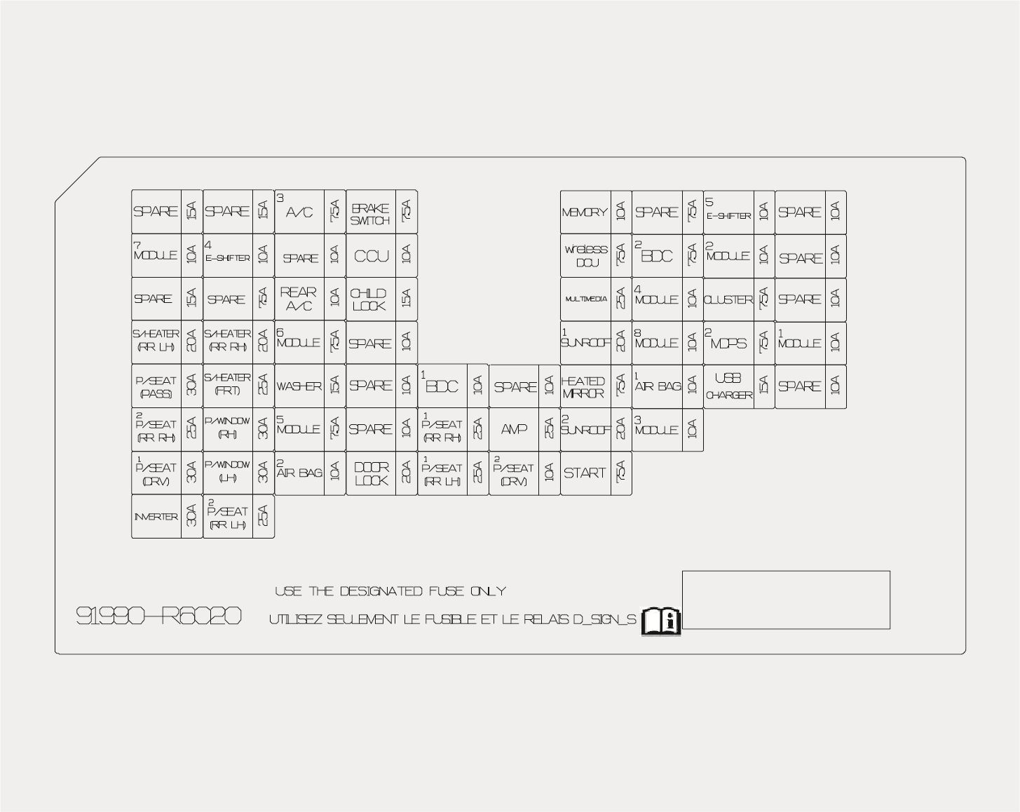
| Position | Amperage [A] | Protected circuit / function |
|---|---|---|
| AAF | 15 | Active air flaps: upper left, upper right and lower |
| A/C3 | 7.5 | Engine-room PTC heater relay; automatic HVAC: front HVAC controller, cabin temperature sensor and control panel; manual HVAC: front HVAC controller |
| BRAKE SWITCH | 7.5 | Body Domain Controller (BDC) and stop lamp switch |
| MEMORY | 10 | Rear HVAC controller, fingerprint identification module, BDC, infotainment socket assembly, front HVAC controller, CDCU, head-up display, ambient lights, front corner radars, door illumination and automatic HVAC panel; with amplifier: low-voltage DC/DC converter |
| E-SHIFTER5 | 10 | Electronic automatic transmission selector |
| MODULE7 | 10 | Engine-room blower relay, diagnostic connector, hazard lamps, rain sensor, in-cabin camera (ICC), powered liftgate, mirrors, Smart Key handles, driver lumbar support, power seats, driver door module and passenger-seat heating/ventilation controls |
| E-SHIFTER4 | 10 | Electronic automatic transmission selector |
| CCU | 10 | Central Communication Unit (CCU) |
| BDC2 | 7.5 | Body Domain Controller (BDC) |
| MODULE2 | 10 | CCU and stop lamp switch |
| REAR A/C | 10 | Rear HVAC controller |
| CHILD LOCK | 15 | Rear-door electric child safety lock and unlock relay |
| MULTIMEDIA | 25 | Without audio amplifier: low-voltage DC/DC converter |
| MODULE4 | 10 | Driver seat module, amplifier, overhead console, auto-dimming mirror, UVC lamp, fingerprint module, ccNC unit, low-voltage DC/DC converter, diagnostic connector, front HVAC controller, wireless chargers 1/2 and automatic HVAC panel |
| CLUSTER | 7.5 | Instrument cluster and head-up display |
| S/HEATER (RR LH) | 20 | Second-row left power seat module |
| S/HEATER (RR RH) | 20 | Second-row right heated seat module |
| MODULE6 | 7.5 | AC power inverter, AC inverter socket, left/right headlamps and auxiliary 12 V lithium battery |
| SUNROOF1 | 20 | Front sunroof motor |
| MODULE8 | 10 | Driver door module |
| MDPS2 | 7.5 | Motor-driven power steering (MDPS/EPS) |
| MODULE1 | 10 | ADAS parking module, BDC, CCU, DCU, ccNC keypad and low-voltage DC/DC converter |
| P/SEAT (PASS) | 30 | Passenger power seat switch |
| S/HEATER (FRT) | 25 | Passenger seat heater in vehicles without a power seat, or passenger seat ventilation module in vehicles with a power seat |
| WASHER | 15 | Multifunction switch and washer system |
| BDC1 | 10 | Driver/passenger Smart Key door handles, Bluetooth module, front/rear left/right UWB modules and BDC |
| wireless DCU | 10 | Wireless DCU module |
| HEATED MIRROR | 7.5 | Driver and passenger power door mirrors |
| AIR BAG1 | 10 | SRS control unit and front passenger occupancy sensor |
| USB CHARGER | 15 | Infotainment socket assembly, left/right luggage compartment USB chargers and driver/passenger USB chargers |
| P/SEAT (RR RH)2 | 25 | Right second-row seat tilt and folding actuator |
| P/WINDOW (RH) | 30 | Right rear power-window safety module and switch, passenger window safety module and switch |
| MODULE5 | 7.5 | Body Domain Controller (BDC) |
| P/SEAT (RR RH)1 | 25 | Right second-row power seat module |
| AMP | 25 | Low-voltage DC/DC converter |
| SUNROOF2 | 20 | Sunroof roller blind motor |
| MODULE3 | 10 | CDCU, driving/parking ADAS modules, dash and console switches, in-cabin camera (ICC), AWD ECM, ADAS front camera, front/rear corner radars and Smart Cruise Control |
| P/SEAT (DRV)1 | 30 | Driver power seat module and switch |
| P/WINDOW (LH) | 30 | Left rear window safety module, driver window safety module and left rear window switch |
| AIR BAG2 | 10 | SRS control unit |
| DOOR LOCK | 20 | Door lock/unlock relays and two-turn unlock function |
| P/SEAT (RR LH)1 | 25 | Left second-row power seat module |
| P/SEAT (DRV)2 | 10 | Driver power seat switch |
| START | 7.5 | BDC and PCM |
| INVERTER | 30 | AC power inverter module |
| P/SEAT (RR LH)2 | 25 | Left second-row seat tilt and folding actuator |
Engine compartment fuses and multi-fuses
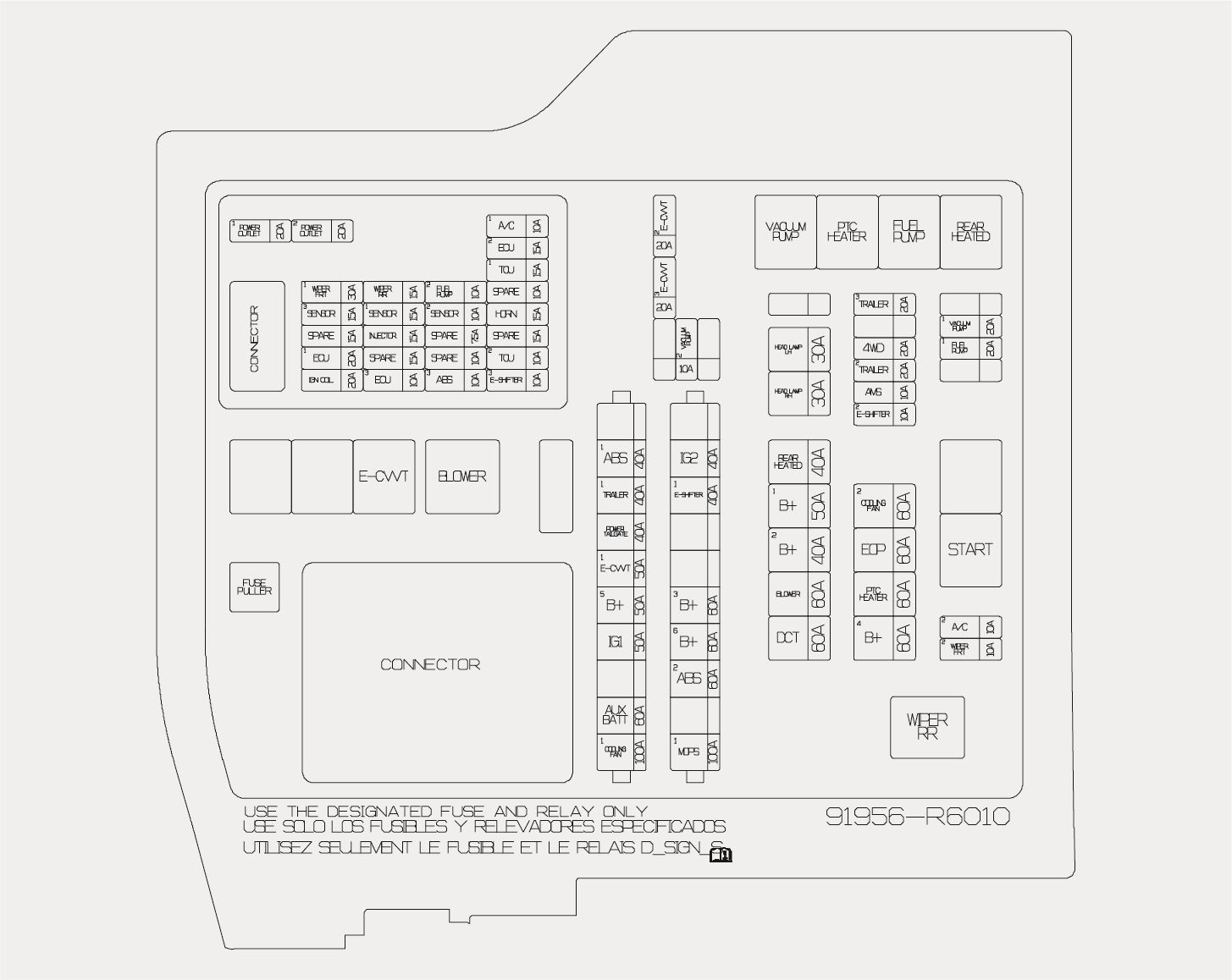
| Position | Amperage [A] | Protected circuit / function |
|---|---|---|
| MULTI FUSE A – ABS1 | 40 | Electronic Stability Control (ESC) module |
| MULTI FUSE A – TRAILER1 | 40 | Trailer wiring connector; manufacturer cover label spells this position TLAILER1 |
| MULTI FUSE A – POWER TAILGATE | 40 | Power tailgate module |
| MULTI FUSE A – E-CVVT1 | 50 | Engine-room E-CVVT relay |
| MULTI FUSE A – B+5 | 50 | Power Distribution Centre (PDC): amplifier, SUNROOF1, SUNROOF2, AIR BAG2, driver seat 2 and wireless DCU |
| MULTI FUSE A – IG1 | 50 | PCB block accessory and IG1 relays |
| MULTI FUSE A – AUX BATT | 60 | Auxiliary 12 V lithium battery |
| MULTI FUSE A – COOLING FAN1 | 100 | Cooling fan motor |
| MULTI FUSE B – IG2 | 30 | Engine-room starter relay and PCB-block IG2 relay |
| MULTI FUSE B – E-SHIFTER1 | 30 | Shift Control Unit (SCU) |
| MULTI FUSE B – B+3 | 60 | PDC: second-row power seats, driver seat, front seats, passenger seat and active air flaps (AAF) |
| MULTI FUSE B – B+6 | 60 | PCB block: ECU2, horn, A/C1, wiper relays and main relay |
| MULTI FUSE B – ABS2 | 60 | Electronic Stability Control (ESC) module |
| MULTI FUSE B – MDPS1 | 80 | Motor-driven power steering (MDPS/EPS) |
| FUSE – REAR HEATED | 40 | Engine-room rear window defogger relay |
| FUSE – B+1 | 50 | PDC circuits IPS4, IPS5, IPS6 and IPS7 |
| FUSE – B+2 | 40 | PDC circuits IPS11 and IPS12 |
| FUSE – BLOWER | 60 | Engine-room blower relay |
| FUSE – DCT | 60 | Transmission Control Module (TCM) |
| FUSE – COOLING FAN2 | 60 | Cooling fan motor |
| FUSE – EOP | 60 | Electric oil pump |
| FUSE – PTC HEATER | 60 | Engine-room PTC heater relay |
| FUSE – B+4 | 60 | PDC: central locking, CCU, brake switch, BDC1, child lock, second-row power seats and IPS13; long-term load latch relay for MULTIMEDIA and MEMORY |
| FUSE – HEAD LAMP LH | 30 | Left headlamp |
| FUSE – HEAD LAMP RH | 30 | Right headlamp |
| FUSE – TRAILER3 | 20 | Trailer control unit |
| FUSE – 4WD | 20 | AWD Electronic Control Module (ECM) |
| FUSE – TRAILER2 | 20 | Trailer wiring connector |
| FUSE – AMS | 10 | Battery sensor |
| FUSE – E-SHIFTER2 | 10 | Shift Control Unit (SCU) |
| FUSE – VACUUM PUMP1 | 20 | Engine-room vacuum pump relay |
| FUSE – FUEL PUMP | 20 | Engine-room fuel pump relay |
| FUSE – A/C2 | 10 | Rear HVAC controller and rear blower motor |
| FUSE – WIPER FRT2 | 10 | BDC and PCM |
| FUSE – E-CVVT2 | 20 | Powertrain Control Module (PCM) |
| FUSE – E-CVVT3 | 20 | Powertrain Control Module (PCM) |
| FUSE – VACUUM PUMP2 | 10 | Electronic Stability Control (ESC) module |
Manufacturer-label note: the TRAILER1 position in Multi Fuse A is shown with the spelling TLAILER1 on the original label. The table keeps the proper circuit name while noting that printed variant.
Trailer, AWD and auxiliary electrical circuits
The trailer wiring uses separate protection for multiple functions. Multi Fuse A TRAILER1 is rated at 40 A for the trailer connector; TRAILER2 is 20 A for another trailer connection, and TRAILER3 is 20 A for the trailer controller. The 4WD fuse (20 A) protects the AWD electronic control module.
The power tailgate has a 40 A POWER TAILGATE fuse in the engine bay, along with cabin control circuits. Cabin USB CHARGER (15 A) supplies the USB charging outlets, including the luggage area ports.
For a smaller Hyundai SUV from the same model year, see the 2025 Hyundai Tucson NX4 fuse diagrams. If comparing seven-seat SUVs, the 2025 Kia Sorento MQ4 has its own circuit assignments and fuse ratings.
What should you check when an electrical device fails?
Start with the fuse assigned to that specific device. If several systems fail at the same time, inspect the relevant B+ feeds and high-current multi-fuses that supply groups of circuits. High-current protection should be checked by a qualified technician. Never replace a blown fuse with one of a higher amperage; repeated failures indicate a fault or overload in the circuit.
Hyundai Santa Fe MX5 2025 FAQ
Where is the fuel pump fuse?
FUEL PUMP (20 A) is in the engine compartment and supplies the fuel pump relay in the E/R fuse box.
Which fuse protects the AWD control module?
The engine-bay 4WD fuse (20 A) feeds the AWD electronic control module.
Where are the USB charging fuses?
The cabin USB CHARGER fuse (15 A) covers the infotainment socket assembly and the front and luggage compartment USB charging outlets.
Do these tables also apply to the Santa Fe Hybrid and Plug-in Hybrid?
No. The hybrid models have additional electrical equipment and require powertrain-specific fuse documentation. Do not work on orange high-voltage wiring.