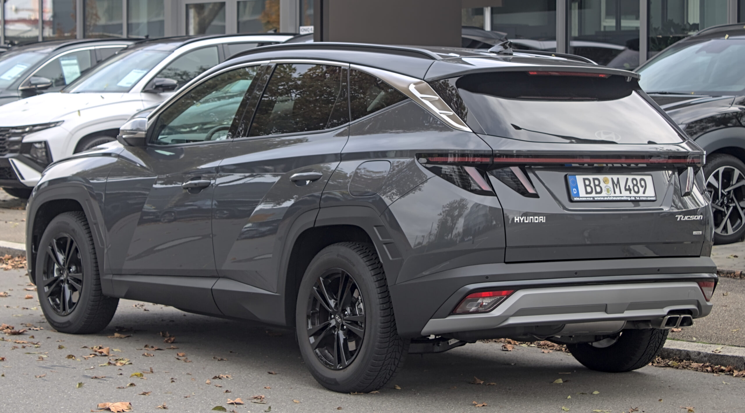
The 2025 Hyundai Tucson NX4 has two main fuse boxes: a cabin fuse panel on the driver’s side and a covered engine-room power distribution box. This guide retains the manufacturer’s fuse identifiers and ratings for the conventional, non-hybrid electrical layout of the 2025 model.
Important: Tucson Hybrid (HEV) and Plug-in Hybrid (PHEV) versions have additional electrical components, including high-voltage equipment, and may differ in fuse placement. The cover label for the precise year, market, engine and equipment of your vehicle takes precedence.
Where are the fuse boxes in a 2025 Hyundai Tucson?
Passenger compartment: on left-hand-drive cars, the cabin panel is behind the removable lower dashboard cover on the driver’s side. Turn the ignition off, remove the access cover and identify the correct fuse using the vehicle’s label.
Engine compartment: the engine-room fuse and relay box is inside the covered power distribution unit beneath the bonnet. Release the lid retainers and compare the markings inside the cover with the table before inspecting a fuse. Secure the cover fully afterward.
Passenger compartment fuse panel
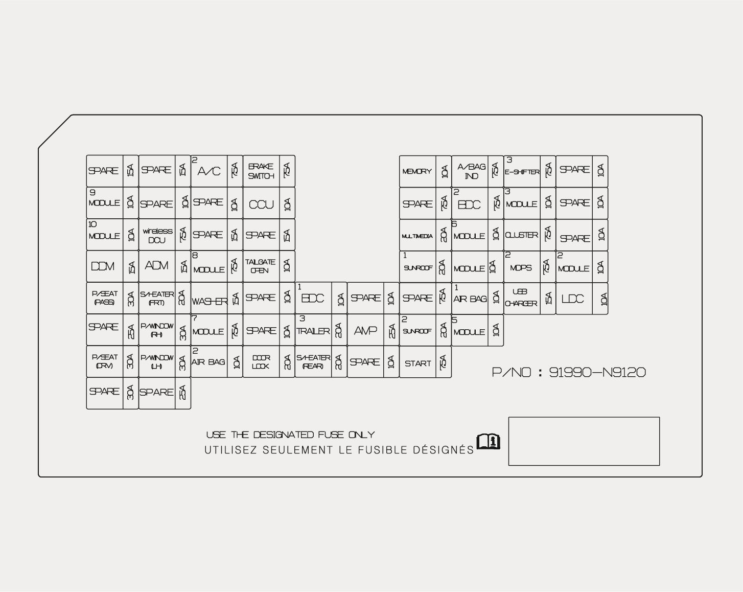
| Position | Amperage [A] | Protected circuit / function |
|---|---|---|
| A/C3 | 15 | Engine-room PTC heater 1 relay; HVAC controller and climate control module |
| BRAKE SWITCH | 7.5 | Brake lamp switch and Body Domain Controller (BDC) |
| MEMORY | 7.5 | Head-up display, BDC, low-voltage DC/DC converter, console and dash ambient lighting, HVAC controls and driver/passenger door illumination |
| A/BAG IND | 7.5 | Overhead console airbag warning indicator |
| E-SHIFTER3 | 7.5 | Shift Control Unit (SCU) and electronic automatic transmission selector |
| MODULE9 | 10 | Power driver seat, seat memory module, power tailgate, rain sensor, diagnostic connector, Smart Key exterior handles and hazard lamps |
| CCU | 10 | Central Communication Unit (CCU) |
| BDC2 | 7.5 | Body Domain Controller (BDC) |
| MODULE3 | 10 | CCU and brake lamp switch |
| MODULE10 | 10 | Interior Camera (ICC) |
| wireless DCU | 7.5 | Wireless DCU module |
| MULTIMEDIA | 20 | Low-voltage DC/DC converter |
| MODULE6 | 10 | Amplifier, wireless phone charger, HVAC, driver seat memory, overhead console, low-voltage DC/DC converter, diagnostics, fingerprint reader, connected car navigation cockpit (ccNC), auto-dimming mirror and ICC |
| CLUSTER | 7.5 | Head-up display and instrument cluster |
| DDM | 15 | Driver door module and power driver mirror |
| ADM | 15 | Power passenger mirror |
| MODULE8 | 7.5 | Auxiliary 12 V lithium battery |
| TAILGATE OPEN | 10 | Power distribution centre (PDC) tailgate-open relay |
| SUNROOF1 | 20 | Sunroof glass motor controller |
| MODULE4 | 10 | Driver door module |
| MDPS2 | 7.5 | Motor Driven Power Steering (MDPS) module |
| MODULE2 | 10 | BDC, low-voltage DC/DC converter, CCU and DCU |
| P/SEAT PASS | 30 | Power passenger seat |
| S/HEATER FRT | 20 | Front seat heating and ventilation |
| WASHER | 15 | Multifunction switch, windshield washer |
| BDC1 | 10 | BDC, Bluetooth modules 1 and 2, Sport mode and front/rear left/right ultra-wideband modules |
| AIR BAG1 | 10 | SRS control module and passenger occupancy sensor |
| USB CHARGER | 15 | Front and rear USB charging outlets |
| LDC | 10 | Amplifier, ccNC, ccNC controls, instrument cluster, head-up display, HVAC, ADAS parking module, rear corner radars and wireless charger |
| P/WINDOW RH | 30 | Right rear window, passenger window safety module and passenger window switch |
| MODULE7 | 7.5 | Body Domain Controller (BDC) |
| TRAILER3 | 20 | Electronic trailer brake controller |
| AMP | 25 | Amplifier supply through low-voltage DC/DC converter |
| SUNROOF2 | 20 | Sunroof sunshade motor controller |
| MODULE5 | 10 | Dashboard switches, front camera, AWD control module, CDCU, automatic transmission selector display, console switches and ADAS parking module |
| P/SEAT DRV | 30 | Power driver seat and seat memory module |
| P/WINDOW LH | 30 | Driver window safety module and left rear window |
| AIR BAG2 | 10 | SRS control module |
| DOOR LOCK | 20 | PDC door locking/unlocking relays and two-turn unlock feature |
| S/HEATER RR | 20 | Rear heated seats |
| START | 7.5 | BDC and PCM |
Engine compartment fuse box
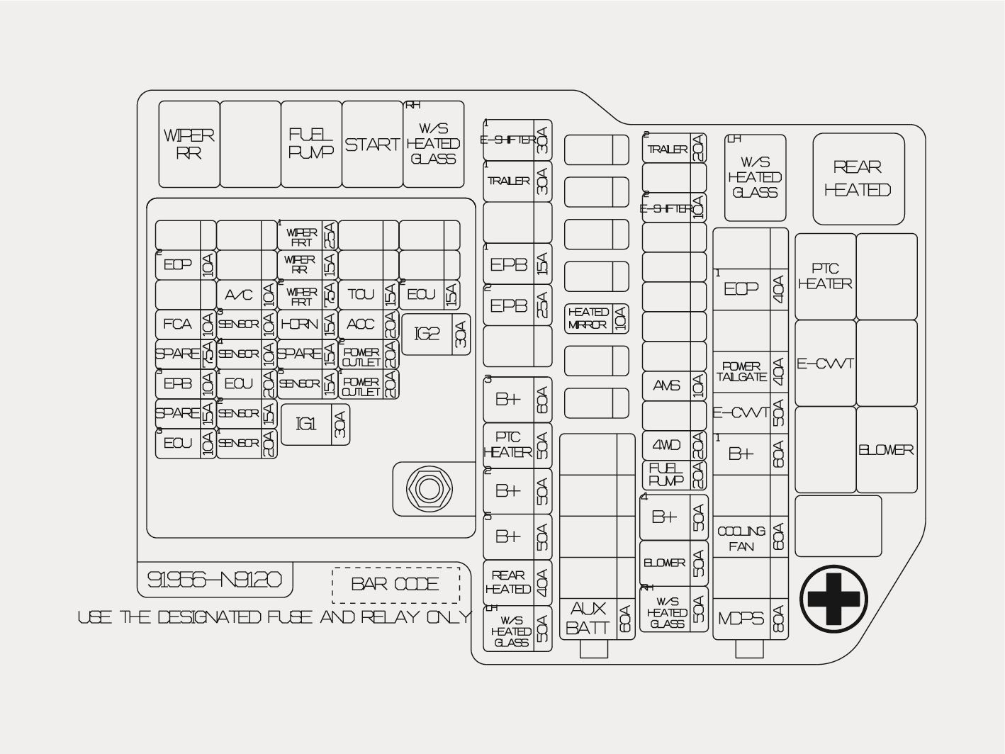
| Position | Amperage [A] | Protected circuit / function |
|---|---|---|
| MDPS | 80 | MULTI FUSE-1: Motor Driven Power Steering (MDPS) module |
| COOLING FAN | 60 | MULTI FUSE-1: Cooling fan controller |
| B+1 | 60 | MULTI FUSE-1: PDC circuits IPS2, IPS3, IPS4, IPS5, IPS6 and IPS7 |
| E-CVVT | 50 | MULTI FUSE-1: Engine-room E-CVVT relay |
| POWER TAILGATE | 40 | MULTI FUSE-1: Power tailgate module |
| EOP1 | 40 | MULTI FUSE-1: Electric oil pump |
| AUX BATT | 60 | MULTI FUSE-2: Auxiliary 12 V lithium battery |
| BLOWER | 50 | Fuse block: Engine-room blower relay |
| B+4 | 50 | Fuse block: PDC: central locking, brake switch, TRAILER3, CCU, BDC1, rear heated seats, liftgate, memory and multimedia |
| FUEL PUMP | 20 | Fuse block: Engine-room fuel pump relay |
| 4WD | 20 | Fuse block: AWD control module |
| AMS | 10 | Fuse block: Battery sensor |
| E-SHIFTER2 | 10 | Fuse block: SCU and electronic automatic transmission selector |
| TRAILER2 | 20 | Fuse block: Trailer module |
| HEATED MIRROR | 10 | Fuse block: Rear window defogger and heated driver/passenger mirrors |
| REAR HEATED | 40 | Fuse block: Engine-room rear window defogger relay |
| B+5 | 50 | Fuse block: PDC: SUNROOF1, SUNROOF2, AIR BAG2 and AMP |
| B+2 | 50 | Fuse block: PDC circuits IPS9, IPS11 and IPS12 |
| B+3 | 60 | Fuse block: PDC: seats, door modules, windows, wireless DCU, front heated seats, MODULE9 and MODULE10 |
| EPB2 | 25 | Fuse block: Electronic Stability Program (ESP) control unit |
| EPB1 | 15 | Fuse block: Electronic Stability Program (ESP) control unit |
| TRAILER1 | 30 | Fuse block: Trailer module |
| E-SHIFTER1 | 30 | Fuse block: Shift Control Unit (SCU) |
| IG1 | 30 | PCB block: PDM IG1 relay |
| IG2 | 30 | PCB block: PDM IG2 relay and engine-room starter relay |
| ECU3 | 10 | PCB block: Powertrain Control Module (PCM) |
| EPB3 | 10 | PCB block: Electronic Stability Program (ESP) control unit |
| FCA | 10 | PCB block: Front radar |
| EOP2 | 10 | PCB block: Electric oil pump |
| SENSOR1 | 20 | PCB block: Ignition coils 1-4 |
| SENSOR2 | 15 | PCB block: Upstream and downstream oxygen sensors |
| ECU1 | 20 | PCB block: Powertrain Control Module (PCM) |
| SENSOR4 | 10 | PCB block: Engine-room fuel pump relay |
| SENSOR3 | 10 | PCB block: Oil control valves, EVAP purge, variable oil pump, variable intake, fan controller, oil level sensor and canister close valve |
| A/C | 10 | PCB block: PCB air conditioning relay |
| SENSOR5 | 15 | PCB block: Fuel injectors 1-4, MPI |
| HORN | 15 | PCB block: Horn relay |
| WIPER FRT2 | 7.5 | PCB block: Powertrain Control Module (PCM) |
| WIPER RR | 15 | PCB block: Rear wiper relay and rear wiper motor |
| WIPER FRT1 | 25 | PCB block: Front wiper motor |
| POWER OUTLET1 | 20 | PCB block: Luggage compartment 12 V power socket |
| POWER OUTLET2 | 20 | PCB block: Front 12 V power socket |
| ACC | 20 | PCB block: PDC, MODULE2 and USB charger |
| TCU | 15 | PCB block: Powertrain Control Module (PCM) |
| ECU2 | 15 | PCB block: Powertrain Control Module (PCM) |
Related 2025 SUVs can have different fuse ratings even when they share some underlying hardware. For comparison, see the 2025 Kia Sportage NQ5 fuse box guide rather than substituting its diagram for the Tucson’s.
Frequently checked fuses: 12 V outlets, wipers and trailer wiring
The front 12 V outlet uses POWER OUTLET2 (20 A), and the luggage compartment 12 V outlet uses POWER OUTLET1 (20 A), both in the under-hood PCB block. USB charging uses the separate cabin USB CHARGER fuse (15 A).
The front wiper circuit includes WIPER FRT1 (25 A) and WIPER FRT2 (7.5 A); the rear wiper uses WIPER RR (15 A). With factory towing equipment, TRAILER1 (30 A) and TRAILER2 (20 A) supply the trailer module, while cabin TRAILER3 (20 A) is associated with the electronic trailer brake controller.
What if a newly fitted fuse blows again?
Never increase the fuse rating. Repeated failure indicates an electrical fault or overload that needs investigation. Check the device plugged into a 12 V outlet, damaged outlet contacts, damp trailer connectors or broken wires around the towbar. If the fuse is intact, also examine the relevant switch, relay or control module.
2025 Hyundai Tucson NX4 fuse box FAQ
Which fuse protects the front power outlet?
POWER OUTLET2 (20 A) in the engine compartment power distribution box. POWER OUTLET1 (20 A) supplies the luggage compartment socket.
Where is the USB charger fuse?
USB CHARGER (15 A) is in the cabin fuse panel. Multimedia equipment and low-voltage converters have separate protected circuits.
Can this diagram be used for a Tucson Hybrid or Plug-in Hybrid?
No, not without confirming the exact electrical layout. Those versions have additional components and model-specific fuse documentation. This guide covers the conventional 2025 NX4 configuration.
Why does my vehicle’s fuse label list fewer circuits?
Hyundai assigns fuses according to the powertrain, trim and market. Blank slots and equipment-specific entries are normal; follow the cover label for the vehicle in front of you.