
Hyundai Getz TB (2002-2005) has two main fuse areas: an engine compartment fuse and relay box beside the battery, and an interior fuse carrier at the end of the dashboard on the driver’s side. The diagrams apply to the earlier, pre-facelift petrol configurations, including 1.1, 1.3 and 1.6-litre versions. A diesel engine, later facelift or extra electrical equipment can have different fuse values and additional circuits.
This article preserves the 58 entries in all three Polish source tables and adds a fourth nine-row table listing each of the named under-bonnet relays. That gives 67 entries across four tables, including spare fuses, separate ABS circuits and both 100/120 A alternator alternatives. Hyundai’s 2003 owner’s manual confirms the circuit code list but directs users to the installed fuse box label for configuration-specific differences. The two original diagrams are retained in their correct positions.
Where are the Getz 2002-2005 fuse boxes?
Engine fuse box: with the ignition switched off and radiator fan stationary, open the bonnet. Locate the protected electrical box close to the battery on the left-hand side of the engine bay, release its plastic cover catches and identify the fuse names from the underside legend. This unit also holds the MAIN, RAD, START, fuel pump and other relays. The alternator 100/120 A link and high-current ABS/EPS protection should only be serviced with the appropriate battery-isolation procedure. Refit the moisture-resistant lid carefully.
Interior panel: open the driver’s door, locate the small access cover on the outer end of the dashboard near the steering wheel and pull it free. On a left-hand-drive car the panel is beside the driver’s knee; right-hand-drive trim access may be mirrored. Compare the labels such as C/LIGHT, AUDIO, FRT WPR and PR/HTD with the original fuse card and use a proper puller rather than metal tools.
Common Getz fuses and circuits
This is an eight-row lookup table for existing circuits in the real fuse boxes, not an extra physical eight-fuse board. Some entries refer to multiple separately rated circuits: for example the blower has BLW 30 A under the bonnet and BLOWER 10 A in the cabin, while ABS has 10, 20 and 40 A feeds. Their current ratings must never be interchanged.
| Pozycja | Amperaż [A] | Chroniony obwód / funkcja |
|---|---|---|
| C/LIGHT | 15 | Passenger fuse for cigarette lighter/front 12 V socket |
| AUDIO | 10 | Passenger fuse for radio and exterior mirror control |
| FRT WPR | 20 | Passenger fuse for front windscreen wiper motor |
| RR/WPR | 15 | Passenger fuse for rear window wiper motor |
| BLW | 30/10 | Heater fan power: BLW 30 A in the engine bay plus BLOWER 10 A in the cabin; two distinct fuses |
| ECU/SNSR | 30/10 | Fuel/engine circuits: ECU 30 A and SNSR 10 A in the engine bay; fuel pump relay is separate |
| ABS | 10/20/40 | ABS electronic and hydraulic feeds: ABS 10 A, ABS1 20 A and ABS2 40 A |
| EPS | 50 | Under-bonnet main power supply for electric power steering |
Engine compartment fuses – 22 complete source rows
Ignition is protected by IGN1 and IGN2 (30 A each). ECU (30 A) supplies the engine control/fuel system; F/PUMP (20 A) serves the fuel-cutoff switch, while a separate F/PUMP relay switches the fuel pump itself. RAD (30 A) supplies the radiator fan. ABS, ABS1 and ABS2 are respectively 10, 20 and 40 A. EPS is 50 A where electric steering is fitted, P/WDW (30 A) protects the power windows and BLW (30 A) the heater motor.
There are two BATT alternator alternatives: 100 A for 1.1-litre petrol and 120 A for the 1.3/1.6 engines. These are not two links installed simultaneously. The other BATT 50 A entry powers headlamps and rear-window demisting and is a separate circuit. Three SPARE positions house unused 15, 10 and 10 A replacement fuses and are retained in the chart.
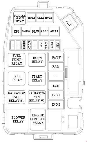
| Pozycja | Amperaż [A] | Chroniony obwód / funkcja |
|---|---|---|
| IGN 2 | 30 | Ignition switch electrical supply (IGN 2) |
| IGN 1 | 30 | Ignition switch and starter relay feed (IGN 1) |
| ECU | 30 | Fuel pump, alternator and engine control module feed |
| F/PUMP | 20 | Automatic fuel cut-off safety switch |
| RAD | 30 | Radiator cooling fan |
| BATT | 50 | Headlamps and heated rear window relay |
| ABS | 10 | Anti-lock braking control system |
| ECU | 10 | Engine ECU additional low-current supply |
| SNSR | 10 | A/C and fuel pump sensor control supply |
| INJ | 15 | Fuel injection valves |
| A/CON | 10 | Air-conditioning electrical control |
| HORN | 10 | Horn |
| ABS1 | 20 | ABS system intermediate power circuit |
| ABS2 | 40 | ABS system high-current power circuit |
| BLW | 30 | Cabin heater and ventilation blower main power |
| P/WDW | 30 | Electric front windows main supply |
| EPS | 50 | Electric power steering main current supply |
| BATT | 100 | Alternator main fuse 100 A for 1.1-litre petrol |
| BATT | 120 | Alternator main fuse 120 A for 1.3/1.6-litre petrol, alternative installation |
| SPARE | 15 | Spare 15 A replacement fuse; no protected device |
| SPARE | 10 | Spare 10 A replacement fuse; no protected device |
| SPARE | 10 | Spare 10 A replacement fuse; no protected device |
Passenger compartment fuses – all 28 original entries
C/LIGHT (15 A) is the cigarette lighter / front 12 V outlet. FRT WPR (20 A) and RR/WPR (15 A) supply front and rear wipers. PR/HTD (30 A) supplies heated rear glass; HTD MIR (10 A) covers mirror heating; D/LOCK (20 A) supplies door locking and AUDIO (10 A) the radio and electric mirrors. Additional separate fuses protect airbags, stop lights, headlights, fog lights, sunroof, seat warmers and DRL where fitted.
A basic car can have vacant optional circuits; this does not mean a fuse has been lost. POWER CONN & R/LP is the 15 A interior lamp/audio/instrument supply. The BLOWER 10 A fuse is a control feed separate from the 30 A blower main link under the bonnet.
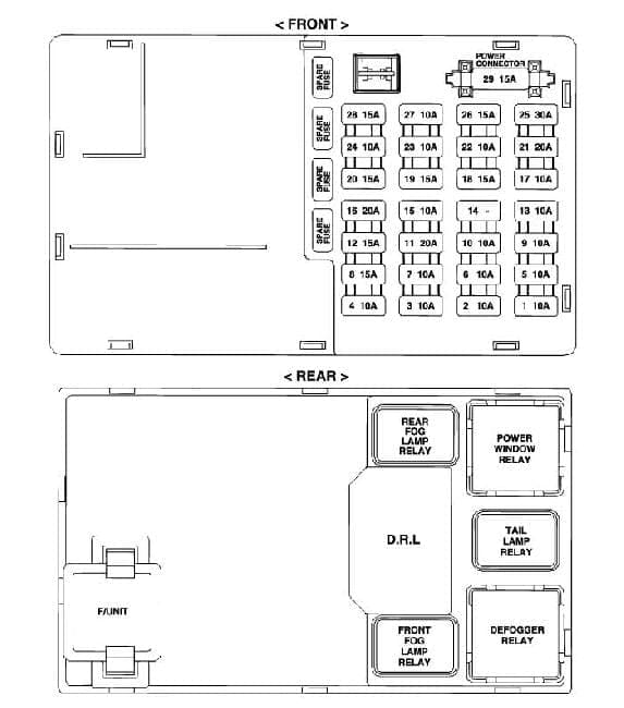
| Pozycja | Amperaż [A] | Chroniony obwód / funkcja |
|---|---|---|
| POWER CONN & R/LP | 15 | Courtesy room lamp, radio and instrument cluster |
| H/LP LH | 15 | Left headlamp and high-beam warning indicator |
| F/FOG | 10 | Front fog lamps, optional |
| H/LP RH | 15 | Right headlamp |
| PR/HTD | 30 | Rear-window demister / defogger |
| BLOWER | 10 | Heater blower controller and sunroof on equipped cars |
| IGNITION | 10 | Front fog lights, ETACM, window electrics and headlamp levelling |
| R/FOG | 10 | Rear fog lamp |
| FRT WPR | 20 | Front windscreen wiper motor |
| HAZARD | 15 | Hazard warning lights and ETACM module |
| STOP | 15 | Brake/stop lights and power windows |
| ECU2 | 15 | Engine electronic control module |
| HTD MIR | 10 | Heated exterior mirrors and rear-window demister |
| S/HTD | 20 | Front seat warmers, if fitted |
| DRL | 10 | Daytime running lamps, market dependent |
| START | 10 | Starter relay and anti-theft system |
| RR/WPR | 15 | Rear windscreen wiper motor |
| D/LOCK | 20 | Door locking and powered sunroof |
| A/BAG | 10 | Airbag SRS electrical controller |
| ECU1 | 10 | PCM/ECU supply and ABS control |
| C/LIGHT | 15 | Cigarette lighter and front 12 V socket |
| CLUSTER | 10 | Instrument panel / gauges |
| TAIL RH | 10 | Right rear/tail position lamps |
| T/SIG | 10 | Turn signals and reversing lamps |
| AUDIO | 10 | Radio and electrically adjustable mirrors |
| A/BAG IND | 10 | Airbag warning indicator circuit |
| TAIL LH | 10 | Left rear/tail position lamps |
| A/C SW | 10 | Air conditioner switch and control |
Under-bonnet relays – all nine named functions
The original engine box illustration identifies MAIN, BLOWER, RAD1, RAD2, START, A/CON, HORN, F/PUMP and B/ALARM relay positions. A relay marked F/PUMP is not a blade fuse labelled F/PUMP 20 A, and RAD1/RAD2 are switching components independent of the RAD 30 A fuse. Relays for an alarm or air conditioning can be absent from a basic car.
| Pozycja | Amperaż [A] | Chroniony obwód / funkcja |
|---|---|---|
| MAIN | – | Main engine electrical supply relay |
| BLOWER | – | Passenger heater blower motor relay |
| RAD1 | – | Radiator cooling fan relay, stage one |
| RAD2 | – | Radiator cooling fan relay, second circuit |
| START | – | Starter motor switching relay |
| A/CON | – | Air conditioning compressor control relay |
| HORN | – | Horn relay |
| F/PUMP | – | Petrol fuel pump relay |
| B/ALARM | – | Vehicle anti-theft alarm relay, if equipped |
Petrol, diesel, alternator and equipment differences
The 2003 Hyundai handbook lists the same named petrol fuse circuits but warns that the label in the installed fuse box is decisive. Diesel Getz versions can have a different engine-bay list, including fuel heating and ECU differences, and later 2006-onward facelift models should not use the older car’s drawing without checking. The BATT 100/120 A main alternator link changes specifically between 1.1 and 1.3/1.6 petrol versions. ABS, EPS, air conditioning, heated seats, daytime-running lights and factory alarm are optional in many markets.
The newer Hyundai i30 FD (2008-2011) has a different electrical architecture; the Hyundai i10 III uses another fuse identification layout. Do not substitute either model’s slot numbers for those printed in the Getz.
Common electrical problems on the Getz
12 V socket dead: inspect cabin C/LIGHT (15 A), then remove the charger and check the socket for metal debris. Blower fan fails: test under-bonnet BLW (30 A), cabin BLOWER (10 A), blower relay and speed regulator. A failed resistor may still leave the highest blower speed working.
No fuel pump operation: check ECU (30 A), SNSR (10 A) and the separate F/PUMP fuel pump relay and measure supply at the pump. Rear window not heating: cabin PR/HTD (30 A), the BATT 50 A feed and glass terminals are relevant.
Front or rear wiper stopped: use cabin FRT WPR (20 A) or RR/WPR (15 A), then inspect the stalk, motor and linkage. Electric steering warning: if equipped, EPS (50 A), battery voltage, grounds and steering ECU require checking. ABS warning: inspect all three fuse feeds ABS, ABS1 and ABS2 before reading the controller fault codes. Never raise the amp rating because a different Hyundai uses a similar circuit name.