
Hyundai Getz TB facelift (2006-2008) uses a fuse and relay box alongside the battery under the bonnet and a separate fuse panel at the driver’s dashboard end. The engine-box diagram differs for gasoline and diesel engines; this article preserves both. The cabin table applies to the standard left-hand-drive (LHD) layout, familiar in Poland. Right-hand-drive (RHD) cars have different physical fuse positions and in several places different current ratings.
The four original tables contain 80 circuit and variant entries: nine quick references, 21 petrol engine fuses, 22 diesel engine fuses and 28 LHD cabin positions. Nine engine relay locations, previously named only in the Polish article’s paragraph, have been added as a separate fifth table, giving 89 total entries. All three original model-specific fuse drawings remain; the diesel BATT 100/120 A discrepancy in the Hyundai factory owner’s manual is explicitly identified below rather than hidden.
Where are the fuse boxes in a Hyundai Getz 2006-2008?
Engine compartment: with ignition and consumers switched off, open the bonnet and locate the large covered fuse/relay carrier beside the battery. Release the cover’s retaining catches, read the component names on the inside of the cover and compare them with the petrol or diesel layout below. Hyundai labels the relays MAIN, BLOWER, RAD1, RAD2, START, A/CON, HORN, F/PUMP and B/ALARM. Keep hands away from the fan even when the engine is not running; use proper electrical isolation to service the 40-100/120 A links.
Passenger compartment: open the driver’s door. On left-hand-drive vehicles the small fuse carrier is behind the removable end cap on the driver’s dashboard side, near the steering wheel. Pull the trim cover away from its clips and identify the named blade fuses. The number printed on a different-market right-hand-drive diagram is not a safe substitute for the label on the installed carrier.
Common fuse and power circuit lookup
These are cross-references to actual circuit labels, not a separate nine-fuse holder. The cigarette lighter is supplied by under-bonnet C/LIGHTER (25 A), while a separate accessory outlet uses cabin P/OUTLET (15 A). The blower has two separate fuses BLW (30 A) and BLOWER (10 A). ABS and fuel-system references likewise list multiple circuits; never choose an amp rating solely from the quick lookup.
| Pozycja | Amperaż [A] | Chroniony obwód / funkcja |
|---|---|---|
| C/LIGHTER | 25 | Cigarette lighter – under-bonnet C/LIGHTER supply |
| P/OUTLET | 15 | Separate 12 V power outlet in the passenger compartment |
| AUDIO | 15 | Radio and electric mirror electronics, where fitted |
| FRT WPR | 20 | Front windscreen wiper motor |
| RR/WPR | 15 | Rear windscreen wiper motor |
| BLW / BLOWER | 30/10 | Cabin ventilation blower: separate main 30 A and control 10 A fuses |
| F/PUMP / ECU / SNSR | 15/30/10 | Fuel supply/engine control: three distinct under-bonnet circuits, not one interchangeable fuse |
| ABS / ABS1 / ABS2 | 10/20/40 | Three separate ABS controller and hydraulic fuses |
| EPS | 50 | Main electric power steering supply, where fitted |
Petrol engine fuse box – all 21 source entries
In the gasoline layout, IGN2 and IGN1 are both 30 A, ECU is 30 A, RAD is 30 A for engine fan power, and BATT 50 A supplies the headlights/rear demister relay. C/LIGHTER (25 A) protects the cigarette lighter, while F/PUMP (15 A) is the automatic fuel cut-off circuit. The injection control INJ uses 15 A, A/CON and HORN are 10 A, EPS is 50 A and P/WDW is 30 A. The factory petrol drawing lists a 100 A BATT alternator main fuse.
ECU-B has a documented 10 A rating, but the Hyundai manual leaves the individual consumer description blank. The translation retains the position without inventing an ECU component that Hyundai did not name.
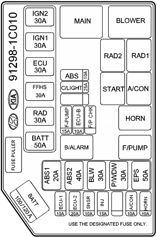
| Pozycja | Amperaż [A] | Chroniony obwód / funkcja |
|---|---|---|
| IGN 2 | 30 | Ignition switch, circuit IGN 2 |
| IGN 1 | 30 | Ignition switch and starter relay, circuit IGN 1 |
| ECU | 30 | Fuel pump, alternator and engine control module |
| RAD | 30 | Radiator cooling fan power |
| BATT | 50 | Headlamps and rear-window defogger relay supply |
| ABS | 10 | Anti-lock brake control electronics |
| C/LIGHTER | 25 | Cigarette lighter power feed |
| F/PUMP | 15 | Automatic fuel shut-off switch – not the separate fuel-pump relay |
| ECU-B | 10 | ECU-B: fuse named in Hyundai manual; individual protected components not specified |
| ABS1 | 20 | ABS system, ABS1 power feed |
| ABS2 | 40 | ABS system, ABS2 higher-current feed |
| BLW | 30 | Heater and ventilation blower motor main power |
| P/WDW | 30 | Electric windows main power supply |
| EPS | 50 | Electric power steering supply, equipped versions |
| ECU-1 | 10 | Engine control module ECU-1 feed |
| ECU-2 | 20 | Engine control module ECU-2 feed |
| SNSR | 10 | Air-conditioning control and fuel-pump related sensor supply |
| INJ | 15 | Fuel injector power |
| A/CON | 10 | Air-conditioning electrical control |
| HORN | 10 | Horn circuit |
| BATT | 100 | Alternator / generator main 100 A power supply on the documented petrol layout |
Diesel engine fuse box – all 22 source entries
The diesel carrier adds FFHS (30 A) for the diesel-specific heating circuit. Its other labelled feeds include IGN1/IGN2 (30 A each), ECU (30 A), RAD (30 A), ABS1/ABS2 (20/40 A), engine blower BLW (30 A), power windows (30 A), EPS (50 A) and the under-bonnet C/LIGHTER (25 A).
Alternator rating discrepancy in the original Hyundai manual: the diesel drawing labels its large BATT fusible link 120 A, but the accompanying factory table specifies 100 A. The old Polish table also lists 100 A. This source table keeps that documented 100 A entry and notes the difference in the description; do not fit either rating until the actual installed strip, original lid and engine variant have been identified.
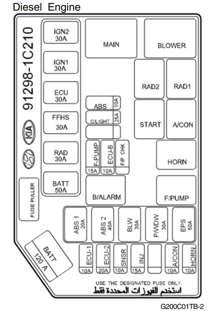
| Pozycja | Amperaż [A] | Chroniony obwód / funkcja |
|---|---|---|
| IGN 2 | 30 | Ignition switch, circuit IGN 2 |
| IGN 1 | 30 | Ignition switch and starter relay, circuit IGN 1 |
| ECU | 30 | Fuel pump, alternator and engine control module |
| FFHS | 30 | FFHS 30 A circuit – diesel fuel heating system, equipment dependent; verify factory FFHS label |
| RAD | 30 | Radiator cooling fan power |
| BATT | 50 | Headlamps and rear-window defogger relay supply |
| ABS | 10 | ABS electronic control |
| C/LIGHTER | 25 | Cigarette lighter main electrical supply |
| F/PUMP | 15 | Automatic fuel cut-off switch |
| ECU-B | 10 | ECU-B fuse; manufacturer handbook does not identify its individual load |
| ABS1 | 20 | ABS first additional power circuit |
| ABS2 | 40 | ABS second high-current power circuit |
| BLW | 30 | Cabin heater blower motor main power |
| P/WDW | 30 | Power window main supply |
| EPS | 50 | Electric power steering main supply, optional |
| ECU-1 | 10 | Engine control ECU-1 supply |
| ECU-2 | 20 | Engine control ECU-2 supply |
| SNSR | 10 | Air conditioning and fuel supply sensor circuit |
| INJ | 15 | Fuel injector electrical supply |
| A/CON | 10 | Air-conditioning electrical controls |
| HORN | 10 | Horn circuit |
| BATT | 100 | Alternator / charging circuit – 100 A in the owner’s-manual list; diesel diagram itself marks the BATT link 120 A, so verify the installed rating |
LHD passenger compartment fuse panel – all 28 original entries
The P/OUTLET (15 A) supplies the cabin accessory power socket, FRT WPR (20 A) the front wipers, RR/WPR (15 A) the rear wiper, AUDIO (15 A) the radio and electric mirrors, PR/HTD (30 A) the rear-window demister and STOP (15 A) the brake lights. BLOWER (10 A) is separate from the 30 A engine-bay blower feed.
Cars without heated seats, powered sunroof, daytime running lights, electric mirrors or factory fog lights may have unused optional circuits. The LHD fuse panel must not be copied from the earlier 2002-2005 Getz, whose accessory labels and rated positions can differ.

| Pozycja | Amperaż [A] | Chroniony obwód / funkcja |
|---|---|---|
| POWER CONN & R/LP | 15 | Passenger courtesy lighting, radio/audio and instrument cluster |
| H/LP LH | 15 | Left headlamp and high-beam tell-tale |
| F/FOG | 10 | Front fog lamps where fitted |
| H/LP RH | 15 | Right headlamp |
| PR/HTD | 30 | Rear-window heating / demister |
| BLOWER | 10 | Heater blower controls and powered sunroof |
| IGNITION | 10 | Fog lamp switches, ETACM, electric windows and beam height adjustment |
| R/FOG | 10 | Rear fog lamp |
| FRT WPR | 20 | Front windscreen wiper motor |
| HAZARD | 15 | Hazard warning lamps and ETACM body controller |
| STOP | 15 | Brake/stop lights and electric window electronics |
| ECU2 | 15 | Engine management ECM |
| HTD MIR | 10 | Heated outside mirrors / rear defogger circuit |
| S/HTD | 20 | Electrically heated front seats, optional |
| DRL | 10 | Daytime running lights, depending on market |
| START | 10 | Starter relay and theft-alarm electronics |
| RR/WPR | 15 | Rear window wiper motor |
| D/LOCK | 20 | Central door locking and electric sunroof |
| A/BAG | 10 | Supplemental Restraint System airbag controller |
| ECU1 | 10 | PCM and ABS control electronic supply |
| P/OUTLET | 15 | Front accessory / 12 V power outlet |
| CLUSTER | 10 | Instrument cluster |
| TAIL RH | 10 | Right parking / rear position lights |
| T/SIG | 10 | Direction indicators and reversing lamps |
| AUDIO | 15 | Audio system and electrically adjustable exterior mirrors |
| A/BAG IND | 10 | Airbag warning indicator supply |
| TAIL LH | 10 | Left parking / rear position lights |
| A/C SW | 10 | Air-conditioning switch and controller |
Engine compartment relays – nine named locations
MAIN controls main engine electrical supply; RAD1 and RAD2 are radiator fan switching relays and are not the RAD 30 A fuse itself. BLOWER feeds cabin ventilation switching. The starter, air-conditioning, horn and fuel pump have their own relay sockets; a B/ALARM relay may be absent when the car lacks the corresponding alarm system.
| Pozycja | Amperaż [A] | Chroniony obwód / funkcja |
|---|---|---|
| MAIN | – | Main power supply relay |
| BLOWER | – | Heating and ventilation blower motor relay |
| RAD1 | – | Engine radiator cooling fan relay, circuit 1 |
| RAD2 | – | Engine radiator cooling fan relay, circuit 2 |
| START | – | Starter control relay |
| A/CON | – | Air-conditioning compressor / controller relay |
| HORN | – | Horn relay |
| F/PUMP | – | Fuel pump relay, distinct from 15 A F/PUMP fuse |
| B/ALARM | – | Anti-theft alarm relay, installed only on equipped vehicles |
Differences between petrol, diesel and steering-wheel markets
The diesel-specific FFHS feed is not present on the petrol carrier. The LHD dashboard has FRT WPR 20 A, PR/HTD 30 A, BLOWER 10 A and CLUSTER 10 A. Hyundai’s RHD table can instead show FRT WPR 30 A, PR/HTD 15 A, BLOWER 15 A and CLUSTER 20 A, as documented for the differently arranged panel. Do not interchange those readings or treat RHD as simply a mirrored copy.
See the earlier Hyundai Getz 2002-2005 fuse chart or the Hyundai Getz 2009-2010 guide, which also lists the RHD panel separately. Similar exterior styling does not establish the same electrical equipment or main BATT fuse.
Common Getz electrical problems
Cigarette lighter is dead: check C/LIGHTER (25 A) under the bonnet, not only cabin P/OUTLET (15 A). The latter is for a separate power outlet. Inspect the socket for metal debris and damaged chargers before replacing a blown fuse.
Cabin blower will not start: engine BLW (30 A) and cabin BLOWER (10 A) are different feeds. Check both before the blower resistor or fan motor. Rear windscreen demister has failed: inspect LHD PR/HTD (30 A) and engine BATT (50 A) supply, then the glass connections.
Engine overheats and the radiator fan is not running: check RAD (30 A), radiator relays RAD1/RAD2, fan connectors and motor. Fuel supply fault: compare the ECU (30 A), SNSR (10 A), F/PUMP (15 A) safety circuit and the F/PUMP relay with the engine model rather than bypassing the fuel cut-off.
Front or rear wipers fail: on LHD vehicles start with FRT WPR (20 A) or RR/WPR (15 A) respectively. ABS warning lamp: inspect all three separate under-bonnet ABS/ABS1/ABS2 supplies (10/20/40 A) and read the stored fault codes. A fuse with the wrong current rating can create a fire risk even if it initially restores power.