
Hyundai Getz TB (2009-2010) has a main fuse and relay carrier beside the battery in the engine compartment and a second panel inside the driver’s dashboard. The under-bonnet board differs between petrol and diesel engines. More importantly, there are different fuse layouts for left-hand-drive (LHD) and right-hand-drive (RHD) vehicles. The RHD panel is not simply a mirrored drawing: several fuse ratings and protected components also differ.
The five tables in the original Polish article contain 107 entries: 9 common-circuit references, 21 petrol engine fuses, 22 diesel engine fuses, 28 LHD passenger fuses and 27 RHD passenger fuses. All have been retained. A sixth table includes nine named engine-bay relays, increasing the guide to 116 total rows. All four original illustrations are retained. The period Hyundai factory manual documents these same equipment families but warns that fuse occupancy is vehicle and market specific; its 2003-2008 edition is a cross-check, not proof that every 2009-2010 car has identical wiring.
How to reach the Getz fuse boxes
Under the bonnet: switch off ignition and all connected electrical equipment and wait for the radiator fan to stop. Locate the fuse housing directly beside the battery. Press the plastic cover retaining tabs, lift the cover and read the printed diagram. Diesel vehicles have the extra FFHS fuse; do not select a petrol drawing to troubleshoot diesel equipment. Refit the cover firmly. High-current BATT, ABS and EPS links must not be bridged and require appropriate battery isolation for servicing.
Passenger compartment: open the driver’s door and look for the removable panel at the outer end of the dashboard closest to the steering wheel. Release its clips, compare the actual 28-position LHD or 27-position RHD label with the drawings and use the fuse puller. Vehicles used in mainland Europe are normally LHD, but imported RHD cars require the other table below. Do not use a left-hand-drive FRT WPR rating on the right-hand-drive board.
Common fuse and electrical circuit lookup
The quick table refers to actual fuses in the two physical boxes. The under-bonnet C/LIGHTER (25 A) protects the cigarette lighter, while cabin P/OUTLET (15 A) supplies a separate accessory power outlet. The blower also has a 30 A power and 10 A LHD control feed. ABS1/ABS2 have their own separate ratings; the numbers in one quick-reference cell never represent alternate fuses that can be swapped freely.
| Pozycja | Amperaż [A] | Chroniony obwód / funkcja |
|---|---|---|
| C/LIGHTER | 25 | Cigarette lighter, under-bonnet 25 A power supply |
| P/OUTLET | 15 | Additional cabin 12 V accessory power socket on LHD versions |
| AUDIO | 15 | Radio and electrically operated exterior mirrors |
| FRT WPR | 20 | Front windscreen wiper motor on LHD cars |
| RR/WPR | 15 | Rear window wiper motor on LHD cars |
| BLW / BLOWER | 30/10 | Heater blower uses distinct 30 A engine-bay and 10 A cabin fuses on LHD |
| F/PUMP / ECU / SNSR | 15/30/10 | Fuel-related safety and engine control, three separate circuits |
| ABS / ABS1 / ABS2 | 10/20/40 | ABS electrical/hydraulic supply, three separately rated fuses |
| EPS | 50 | Electronic power-assisted steering, equipment dependent |
Gasoline engine fuse box – 21 entries
Petrol cars have IGN1 and IGN2 (30 A each) for ignition, ECU (30 A) for engine control/fuel supply, RAD (30 A) for radiator cooling, BATT (50 A) for headlamps and rear defogging, and separate ABS 10 A, ABS1 20 A and ABS2 40 A protection. C/LIGHTER (25 A) supplies the front lighter, while F/PUMP (15 A) covers the automatic fuel cut-off circuit. The alternator main BATT fuse is 100 A in this source arrangement.
ECU-B (10 A) is listed by Hyundai but without a precise component description in the factory table. A mechanic should use the relevant engine wiring diagram rather than inventing one particular load for that slot.
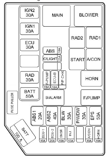
| Pozycja | Amperaż [A] | Chroniony obwód / funkcja |
|---|---|---|
| IGN 2 | 30 | Ignition switch circuit 2 |
| IGN 1 | 30 | Ignition switch circuit 1 and starter relay |
| ECU | 30 | Fuel pump, alternator and engine ECM |
| RAD | 30 | Radiator cooling fan |
| BATT | 50 | Headlamps and heated rear-screen relay |
| ABS | 10 | Anti-lock brake electronic controller |
| C/LIGHTER | 25 | Front cigarette lighter (not the separate cabin accessory outlet) |
| F/PUMP | 15 | Automatic fuel cut-off control |
| ECU-B | 10 | ECU-B 10 A position, specific electrical load not stated in factory table |
| ABS1 | 20 | ABS first supplementary control circuit |
| ABS2 | 40 | ABS main high-current power circuit |
| BLW | 30 | Heating and ventilation blower motor |
| P/WDW | 30 | Electric power windows |
| EPS | 50 | Electric power steering main supply |
| ECU-1 | 10 | Engine control module ECU-1 circuit |
| ECU-2 | 20 | Engine control module ECU-2 circuit |
| SNSR | 10 | Air conditioning and fuel-system sensor power |
| INJ | 15 | Fuel injectors |
| A/CON | 10 | Air-conditioning electrical control |
| HORN | 10 | Horn |
| BATT | 100 | Alternator BATT main power, documented 100 A petrol configuration |
Diesel engine fuse box – 22 entries
The diesel diagram adds FFHS (30 A) for its additional fuel-heating circuit. ECU-1 (10 A), ECU-2 (20 A), SNSR (10 A), INJ (15 A), BLW (30 A), P/WDW (30 A) and EPS (50 A) are each separately protected. The two ABS high-current circuits are still separate from the 10 A ABS electronic feed.
Factory BATT discrepancy: the older Hyundai manual’s diesel diagram marks its charging link 120 A, whereas the printed accompanying table states 100 A, as does the Polish 2009-2010 source. The table below preserves the archival 100 A figure while recording the discrepancy; match the physical strip and engine specification before installing a replacement.

| Pozycja | Amperaż [A] | Chroniony obwód / funkcja |
|---|---|---|
| IGN 2 | 30 | Ignition switch circuit 2 |
| IGN 1 | 30 | Ignition switch circuit 1 and starter relay |
| ECU | 30 | Fuel pump, alternator and engine ECM |
| FFHS | 30 | FFHS diesel fuel heating circuit, equipment dependent |
| RAD | 30 | Radiator cooling fan power |
| BATT | 50 | Headlamps and heated rear-window relay |
| ABS | 10 | ABS electronic controller |
| C/LIGHTER | 25 | Cigarette lighter main power |
| F/PUMP | 15 | Automatic fuel cut-off switch circuit |
| ECU-B | 10 | ECU-B protected circuit; manual does not name the individual load |
| ABS1 | 20 | ABS supplementary 20 A circuit |
| ABS2 | 40 | ABS high-current 40 A circuit |
| BLW | 30 | Heating and ventilation blower motor |
| P/WDW | 30 | Electric power-window main feed |
| EPS | 50 | Electronic power steering circuit |
| ECU-1 | 10 | Engine electronics ECU-1 |
| ECU-2 | 20 | Engine electronics ECU-2 |
| SNSR | 10 | Air-conditioning and fuel-system sensor control |
| INJ | 15 | Fuel injectors |
| A/CON | 10 | Air-conditioning control feed |
| HORN | 10 | Horn circuit |
| BATT | 100 | Diesel alternator main BATT link: the old source table states 100 A; original Hyundai diesel drawing shows 120 A, so verify fitted rating |
Left-hand-drive (LHD) passenger fuses – all 28 positions
The P/OUTLET (15 A) provides an additional 12 V socket. FRT WPR (20 A) protects the front wiper motor, RR/WPR (15 A) the rear wiper, PR/HTD (30 A) the heated rear window, BLOWER (10 A) the heater fan control and CLUSTER (10 A) the instruments. AUDIO is 15 A and D/LOCK 20 A on this LHD board.

| Pozycja | Amperaż [A] | Chroniony obwód / funkcja |
|---|---|---|
| POWER CONN & R/LP | 15 | Interior courtesy lamps, radio and instrument panel |
| H/LP LH | 15 | Left headlamp and high-beam indicator |
| F/FOG | 10 | Optional front fog lamps |
| H/LP RH | 15 | Right headlamp |
| PR/HTD | 30 | Rear-window heater/demister |
| BLOWER | 10 | Cabin blower controls and electric sunroof if installed |
| IGNITION | 10 | Fog lamps, ETACM body controller, electric windows and headlamp levelling |
| R/FOG | 10 | Rear fog lamp |
| FRT WPR | 20 | Front windscreen wiper motor |
| HAZARD | 15 | Hazard warning lamps and ETACM |
| STOP | 15 | Brake lights and power-window electrical control |
| ECU2 | 15 | Engine ECM feed |
| HTD MIR | 10 | Heated exterior mirrors / rear-screen defogger |
| S/HTD | 20 | Optional heated front seats |
| DRL | 10 | Daytime running lights on equipped markets |
| START | 10 | Starter relay and anti-theft alarm |
| RR/WPR | 15 | Rear wiper motor |
| D/LOCK | 20 | Door central locking and electric sunroof |
| A/BAG | 10 | Airbag controller |
| ECU1 | 10 | PCM engine control and ABS electronic input |
| P/OUTLET | 15 | Separate 12 V accessory power outlet |
| CLUSTER | 10 | Instrument cluster |
| TAIL RH | 10 | Right tail and parking lamps |
| T/SIG | 10 | Direction indicators and reversing lights |
| AUDIO | 15 | Radio/audio unit and electric exterior mirrors |
| A/BAG IND | 10 | Airbag warning indicator |
| TAIL LH | 10 | Left tail and parking lamps |
| A/C SW | 10 | Air-conditioning switch and control electronics |
Right-hand-drive (RHD) cabin fuse panel – all 27 positions
Hyundai’s separate RHD chart lists FRT WPR (30 A), RR/WPR (20 A), CLUSTER (20 A), BLOWER (15 A), PR/HTD (15 A), R/FOG (15 A) and S/HTD (15 A). These differ from the LHD fuse card, and some other positions have different physical placement or functions.
The manufacturer’s RHD table does not specify an amperage for A/BAG, D/LOCK, F/FOG, H/LP LH or POWER CONN & R/LP in the available list. Those entries remain marked “-” below rather than being filled with ratings from LHD or a different model year. The diagram must be compared with the actual installed fuse cover before work.

| Pozycja | Amperaż [A] | Chroniony obwód / funkcja |
|---|---|---|
| A/C SW | 10 | Air-conditioning electrical controller |
| TAIL LH | 10 | Left tail and parking lamp |
| A/BAG IND | 10 | Airbag warning lamp |
| AUDIO | 15 | Radio/audio and electric exterior mirrors |
| T/SIG | 10 | Direction indicators and reversing light |
| TAIL RH | 10 | Right tail and parking lamp |
| CLUSTER | 20 | Instrument cluster – 20 A on this RHD chart |
| P/OUTLET | 15 | 12 V power outlet |
| ECU1 | 10 | Engine PCM and ABS controller |
| A/BAG | – | Airbag system; amperage not stated in manufacturer’s RHD table |
| D/LOCK | – | Door locking and electric sunroof; manufacturer leaves this RHD amp value unspecified |
| RR/WPR | 20 | Rear wiper motor – 20 A for this RHD panel |
| START | 10 | Starter relay and theft alarm |
| S/HTD | 15 | Heated front seats, if fitted |
| HTD MIR | 20 | Heated mirrors / rear-window defroster |
| ECU2 | 10 | Engine management ECM |
| STOP | 10 | Stop/brake light circuit |
| HAZARD | 10 | Hazard warning lamps and ETACM |
| FRT WPR | 30 | Front windscreen wiper motor – 30 A for this RHD panel |
| R/FOG | 15 | Rear fog lamp – 15 A for this RHD panel |
| IGNITION | 10 | Ignition, ETACM, fog lamps, electric windows and headlamp levelling |
| BLOWER | 15 | Heater blower and electric sunroof – 15 A |
| PR/HTD | 15 | Heated rear-window defogger – 15 A |
| H/LP RH | 15 | Right headlamp |
| F/FOG | – | Front fog lamp, rating not supplied in manufacturer’s RHD list |
| H/LP LH | – | Left headlamp/high-beam indicator, rating not supplied in manufacturer’s RHD list |
| POWER CONN & R/LP | – | Interior courtesy lamps, audio and cluster, rating not stated in the RHD list |
Engine compartment relays – nine original positions
MAIN supplies the engine electronics; RAD1/RAD2 serve the radiator fan stages; START controls cranking; BLOWER the cabin motor; A/CON the air conditioning; HORN the horn and F/PUMP the fuel pump. The B/ALARM position is fitted only with the corresponding factory alarm. Relay names and fuse names are separate even where identical, for example F/PUMP.
| Pozycja | Amperaż [A] | Chroniony obwód / funkcja |
|---|---|---|
| MAIN | – | Main engine electrical supply relay |
| BLOWER | – | Cabin heating and ventilation blower relay |
| RAD1 | – | Engine radiator cooling fan relay, circuit 1 |
| RAD2 | – | Engine radiator cooling fan relay, circuit 2 |
| START | – | Starter control relay |
| A/CON | – | Air-conditioning compressor relay |
| HORN | – | Horn relay |
| F/PUMP | – | Fuel pump relay, separate from 15 A F/PUMP fuse |
| B/ALARM | – | Factory alarm relay on equipped cars |
Model and market variations that matter
The Getz’s similar-looking outer body remained in production through 2010, but factory equipment and markets can change electrical assignments. An LHD car is not electrically identical to an RHD model; compare the wiper, rear demister and instrument cluster ratings specifically. The diesel FFHS is not in the petrol engine box, and some cars lack electric steering, heated seats, factory fog lights, DRL or alarm relays.
For earlier years see the verified 2002-2005 Hyundai Getz and 2006-2008 Getz guides. The latter already explains the original Hyundai diesel alternator discrepancy. Avoid assigning a fuse based solely on another Getz’s registration year.
Common Hyundai Getz electrical issues
Front cigarette lighter stops: inspect C/LIGHTER (25 A) under the bonnet. If the separate accessory socket fails, inspect P/OUTLET (15 A) in the cabin. A metallic object or damaged charger inside either socket may cause repeat fuse failure.
Front windscreen wipers fail: use FRT WPR 20 A on LHD, but 30 A on the documented RHD panel, then check the stalk and motor. Rear wiper fails: RR/WPR is 15 A LHD or 20 A RHD. Never solve the mismatch by increasing the fuse installed in the other carrier.
Rear-window demister fails: LHD PR/HTD is 30 A; the RHD factory listing shows 15 A. Also inspect the engine BATT 50 A feed, glass terminals and demister relay. Heater blower stopped: BLW 30 A in the engine bay plus BLOWER 10 A LHD or 15 A RHD, followed by the speed resistor and motor.
ABS warning: inspect the ABS 10 A, ABS1 20 A and ABS2 40 A engine-bay circuits before reading stored codes. Engine cranks but will not start: check ECU 30 A, SNSR 10 A, F/PUMP 15 A safety circuit and the F/PUMP relay, then diagnose the fuel supply and engine management. A diesel also requires checking the separate FFHS system if cold-weather symptoms are present.