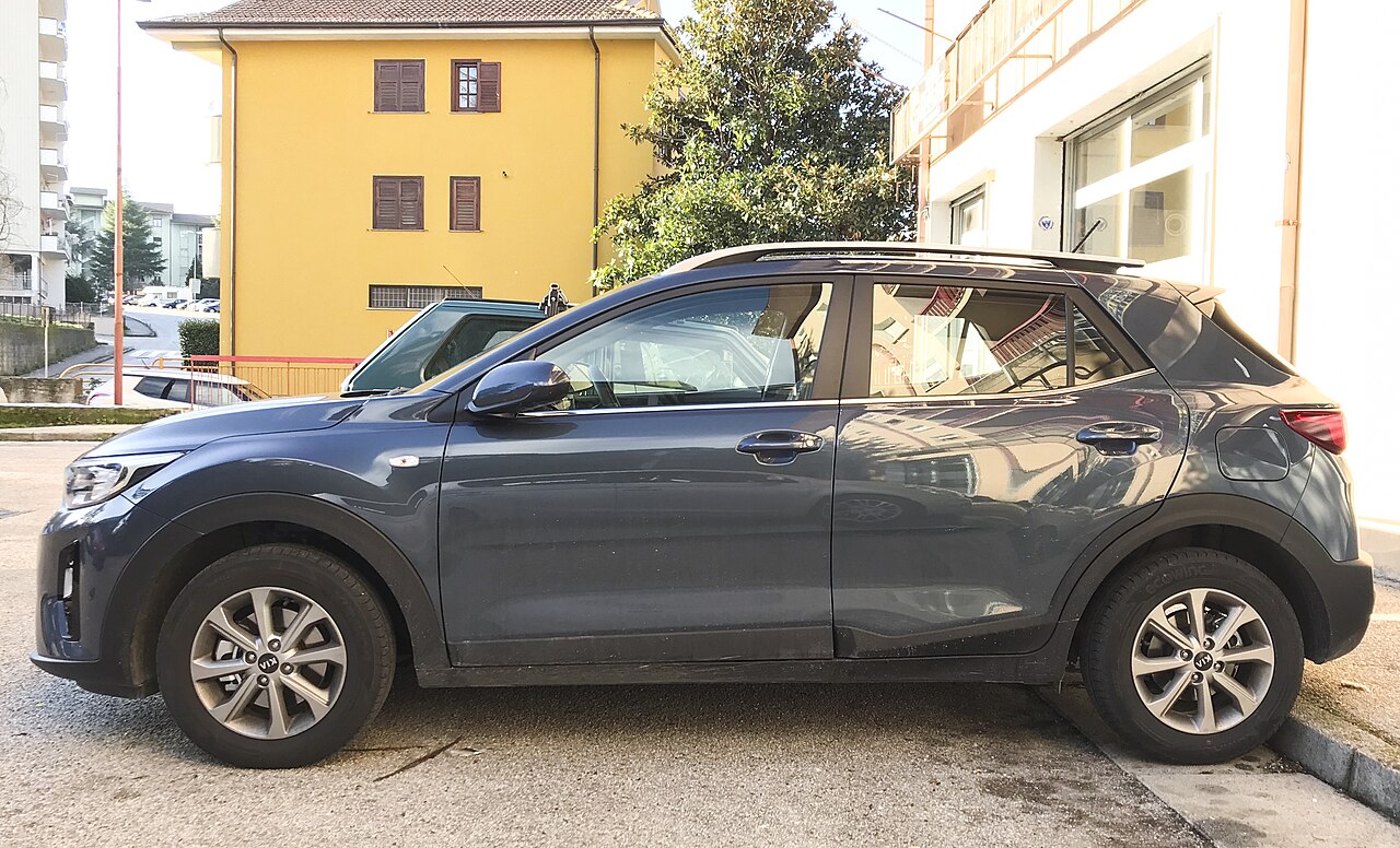
Kia Stonic YB (2018), 1.0 T-GDi has a fuse and relay panel beneath the driver’s side of the dashboard and a main power-distribution box alongside the battery under the bonnet. Some variants have an additional electric PTC heater module. The under-bonnet diagram in this article is specific to the 1.0-litre turbocharged petrol engine; it must not be treated as the diagram for the 1.2 / 1.4 MPI petrol or diesel Stonic.
These four complete tables preserve all 94 documented entries: 50 cabin positions and alternative arrangements, 31 engine compartment fuse circuits, 12 relays and one optional PTC heater position. Cabin numbers 1-48 are editorial table order rather than guaranteed numbers moulded into the fuse carrier. Similarly, P1-P3 and R1-R12 help identify entries and may not be printed beside the physical slots.
Where are the 2018 Kia Stonic fuse boxes?
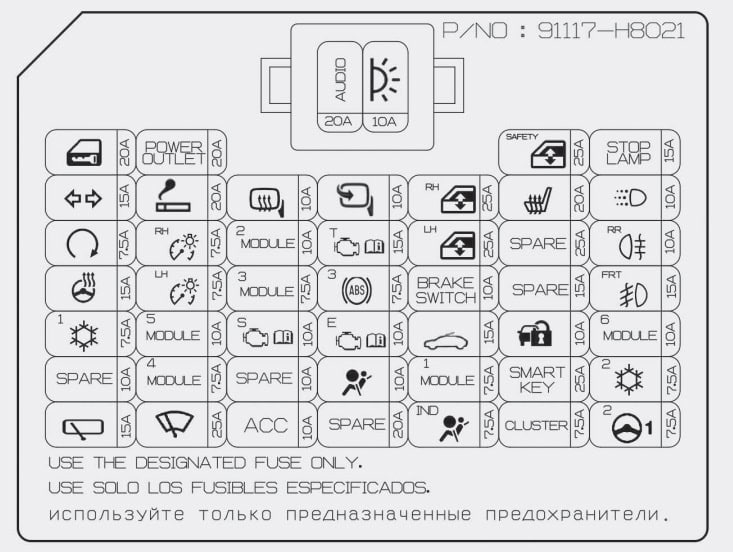
Dashboard fuse box: switch the ignition and all electrical devices off. Open the driver’s door, locate the access cover on the lower side of the dashboard by the footwell, and remove the cover to expose the factory fuse label. Use the plastic fuse puller supplied in the under-bonnet box rather than a metal tool. Replace a faulty blade fuse with exactly the same rating and refit the cover.
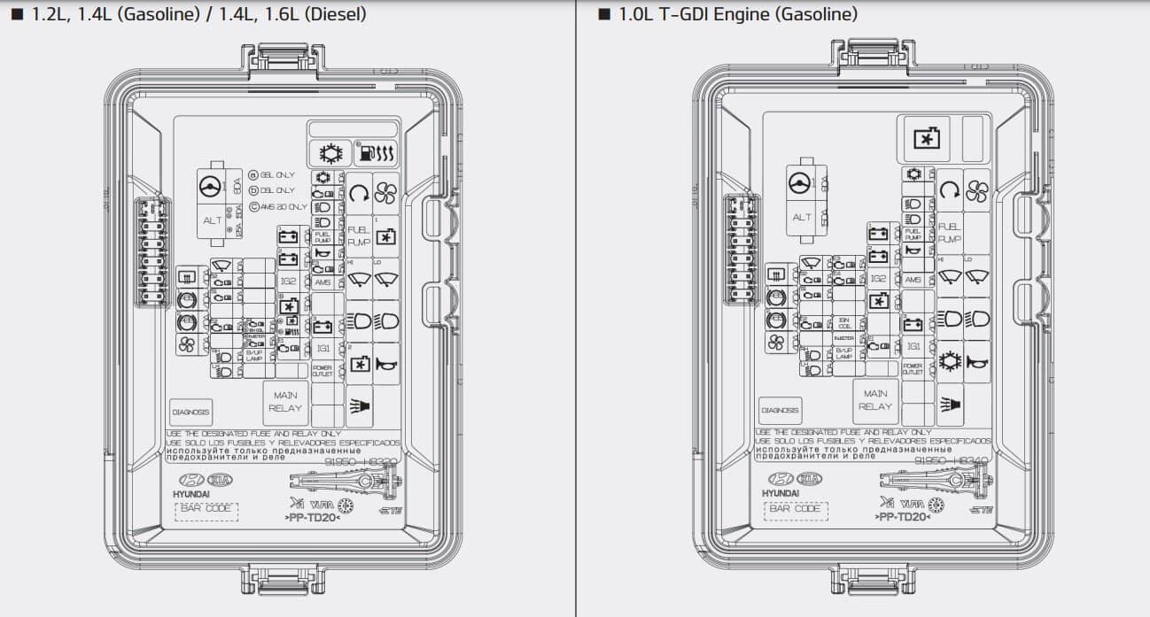
Under the bonnet: find the main fuse and relay box beside the battery. Press the lid clip, lift the cover and match the original symbol and amperage to the correct 1.0 T-GDi layout below. High-current ALT and MDPS links should only be inspected with the manufacturer’s electrical isolation procedure.
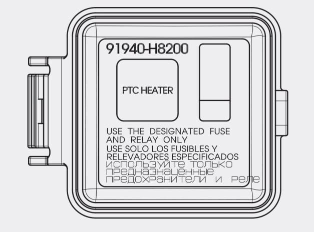
PTC option: on equipped cars, an additional PTC HEATER fuse cover may be fitted within the engine compartment. The specified housing is identified as 91940-H8200. An absent heater housing is normal on a vehicle without this equipment.
Kia Stonic 2018 passenger fuse panel – 50 entries
The cabin list retains factory spare fuses, a vacant slot and two mutually exclusive installations. The front wiper fuse can be shown as 20 or 25 A on different equipment charts. Another position may hold a spare 20 A fuse or a 10 A Tyre Pressure Monitoring System (TPMS) circuit. Do not swap these values between vehicles; use the printed legend fitted to the car.
| Pozycja | Amperaż [A] | Chroniony obwód / funkcja |
|---|---|---|
| 1 | 20 | AUDIO – factory radio and navigation head unit |
| 2 | 10 | MODULE – cabin lights, mirrors, climate, BCM, rain sensor and diagnostics |
| 3 | 20 | DOOR LOCK – central locking and luggage hatch release relays |
| 4 | 15 | BCM / SLM – body controller and locking unit |
| 5 | 7.5 | START / SMART KEY – immobiliser, smart key, engine controller and starter relay |
| 6 | 15 | HEATED STEERING – heated steering wheel, where installed |
| 7 | 7.5 | A/C – climate controller and blower relay control |
| 8 | 10 | SPARE – spare replacement fuse, not an active electrical circuit |
| 9 | 15 | REAR WIPER – rear wiper motor and relay |
| 10 | 20 | POWER OUTLET – 12 V accessory socket |
| 11 | 20 | CIGAR LIGHTER – cigarette lighter 12 V socket |
| 12 | 7.5 | TAIL RH – right position/tail lights and instrument lighting |
| 13 | 7.5 | TAIL LH – left position/tail lights and glovebox lamp |
| 14 | 10 | MODULE 5 – headlamp relays, BCM, seat heating and rain sensor |
| 15 | 7.5 | Body controller, locking unit and Smart Key |
| 16 | 20 | FRONT WIPER – windscreen wiper, earlier documented 20 A option |
| 16 | 25 | FRONT WIPER – alternate fuse-card rating of 25 A; match the fitted label |
| 17 | 10 | Exterior mirror adjustment and signals to climate and engine controllers |
| 18 | 10 | BCM, dashboard switches and forward collision avoidance |
| 19 | 7.5 | Front console, heated seats, audio, navigation and headlamp levelling |
| 20 | 20 | SPARE – spare 20 A fuse in one panel configuration |
| 20 | 10 | TPMS – alternate 10 A tyre pressure monitor supply, not a 20 A spare |
| 21 | 10 | SPARE – spare 10 A replacement fuse |
| 22 | 10 | Accessory outlet relay, USB charger, multimedia, DC-DC converter and BCM |
| 23 | 10 | Daytime running lamp relay (DRL) |
| 24 | 15 | Speed and brake switches, automatic transmission selector and range sensor |
| 25 | 7.5 | ABS / ESC controller and diagnostics connector |
| 26 | 10 | ECM / PCM, immobiliser and Smart Key |
| 27 | 10 | SRS airbag controller and front passenger occupancy sensor |
| 28 | 10 | SPARE – spare 10 A replacement fuse |
| 29 | 25 | Power window switches, including passenger window in left-hand-drive cars |
| 30 | 25 | Main power window switch |
| 31 | 10 | Smart Key module and stop-lamp switch |
| 32 | 15 | Electric sunroof drive, where fitted |
| 33 | 7.5 | Key interlock and BCM / SLM control modules |
| 34 | 7.5 | Instrument cluster, circuit one |
| 35 | 25 | Driver’s power-window anti-pinch module |
| 36 | 20 | Front heated seat control unit |
| 37 | 25 | SPARE – spare 25 A replacement fuse |
| 38 | 15 | SPARE – spare 15 A replacement fuse |
| 39 | 10 | Immobiliser module |
| 40 | 25 | Smart Key control unit |
| 41 | 7.5 | Instrument cluster, circuit two |
| 42 | 15 | Electronic stop signal controller |
| 43 | – | Unoccupied fuse slot |
| 44 | 10 | Rear fog light relay |
| 45 | 15 | Front fog light relay, if equipped |
| 46 | 10 | Key interlock and front centre-console switches |
| 47 | 7.5 | Air conditioning controller |
| 48 | 7.5 | Motor Driven Power Steering (MDPS) controller |
Engine compartment fuses – 1.0 T-GDi petrol
The factory illustration prints two different engine arrangements next to one another. For the 1.0 T-GDi petrol engine use the right-hand layout. It includes engine control, turbocharger oxygen sensors and solenoids, ABS/ESC, headlights, cooling and the main cabin and steering power feeds. The 31-row list retains all manufacturer ratings and circuits, including separate right and left headlamp protection.
| Pozycja | Amperaż [A] | Chroniony obwód / funkcja |
|---|---|---|
| MDPS | 80 | MDPS – main electric steering protection |
| ALT | 150 | ALT – alternator distribution to heated rear window, ABS1, ABS2 and blower feeds |
| RR DEF | 40 | RR DEF – heated rear-window relay supply |
| ABS1 | 40 | ABS1 – first ABS / ESC main controller feed |
| ABS2 | 40 | ABS2 – second ABS / ESC feed and multipurpose inspection connector |
| BLOWER | 40 | BLOWER – cabin heater / air conditioning blower relay |
| WIPER | 10 | WIPER – front wiper motor, multifunction switch and slow-speed relay |
| S2 | 10 | S2 – engine cooling fan relay control |
| S1 | 10 | S1 – upstream and downstream oxygen sensors, turbo recirculation solenoid |
| E2 | 15 | E2 – ECM, oil control valves, purge solenoid and A/C compressor ECV relay |
| RH | 10 | RH – right headlamp |
| LH | 10 | LH – left headlamp |
| E3 | 15 | E3 – ECM power circuit |
| E4 | 15 | E4 – ECM power circuit |
| IGN | 20 | IGN – petrol ignition coils |
| INJ | 15 | INJ – fuel pump relay and ECM engine injection supply |
| B/UP | 10 | B/UP – reversing lamp switch |
| P1 | 40 | P1 – primary power feed to interior fuse junction block |
| P2 | 50 | P2 – interior fuse block and electric window relay feed |
| IG2 | 40 | IG2 – ignition switch and IG2 relay supply |
| FAN | 60 | FAN – main engine cooling fan relay supply |
| E1 | 30 | E1 – engine E3, E4 and main relay supply |
| A/C | 10 | A/C – compressor electronic control valve relay |
| HEAD | 20 | HEAD – main headlamp relay |
| HI | 20 | HI – main-beam headlamp relay |
| FUEL | 20 | FUEL – fuel pump relay circuit |
| HORN | 15 | HORN – horn and burglar-alarm horn relays |
| AMS | 10 | AMS – battery monitoring sensor |
| P3 | 40 | P3 – interior fuse block and tail lamp relay feed |
| IG1 | 40 | IG1 – ignition switch, IG1 and ACC relay supply |
| OUT | 40 | OUT – power outlet relay supply |
Main engine compartment relays
The manufacturer’s manual identifies the starter, fuel pump, windscreen wiper high- and low-speed circuits, headlamps, horn, air conditioning, cooling fan and engine main relay. R1-R12 below are an editorial order of these 12 items, not verified physical socket markings.
| Pozycja | Amperaż [A] | Chroniony obwód / funkcja |
|---|---|---|
| R1 | – | Starter motor relay |
| R2 | – | Air conditioning blower relay |
| R3 | – | Fuel pump relay |
| R4 | – | Windscreen wiper high-speed relay |
| R5 | – | Windscreen wiper low-speed relay |
| R6 | – | Main-beam headlamp relay |
| R7 | – | Main headlamp relay |
| R8 | – | Air conditioning compressor ECV relay |
| R9 | – | Horn relay |
| R10 | – | Burglar-alarm horn relay |
| R11 | – | Engine main ECU relay, MINI type |
| R12 | – | Radiator cooling fan relay, MINI type |
Supplementary electric PTC heater
Some 1.0 T-GDi installations include a separate PTC electric heater cover. In the illustrated manual section, no universal amp rating is given for this position. The rating therefore remains unspecified rather than being borrowed from a diesel or 1.4 MPI diagram.
| Pozycja | Amperaż [A] | Chroniony obwód / funkcja |
|---|---|---|
| PTC | – | Optional PTC electrical cabin heater, supplementary housing 91940-H8200. The manual’s pictured section does not establish a universal amp rating |
Differences between Stonic engines and equipment
Other Stonic engines, including 1.2 MPI, 1.4 MPI and diesel versions, use different engine management, glow plug and cooling circuits. Cars with Smart Key, rain sensors, heated steering, forward collision assistance and factory alarm systems can also have a different occupied set of cabin fuses.
Although Kia shares components with related Hyundai models, this does not make fuse panel diagrams interchangeable. In particular, petrol and diesel engine-bay layouts from a general Stonic owner manual must not be substituted for the 1.0 T-GDi fuse holder.
Useful Kia Stonic 2018 fault checks
12 V outlet or cigarette lighter stopped working: look for the 20 A POWER OUTLET or 20 A CIGAR LIGHTER circuit in the cabin. Under the bonnet, the 40 A OUT circuit feeds the outlet relay. Remove chargers and check for a short in the socket before replacing a fuse.
Front wipers not operating: check the installed 20 / 25 A cabin wiper fuse, the 10 A WIPER control feed under the bonnet and the separate high/low-speed relays. A repeatedly blown fuse can be caused by a stiff linkage or failing motor.
Audio system dead: inspect the 20 A AUDIO supply and the 10 A ACC circuit, then check the system ground and connections. One headlamp failed: the engine carrier has 10 A RH and LH protection; also inspect the bulb and connector.
Horn silent: under-bonnet HORN (15 A) and horn relay. Power steering warning: high-current MDPS (80 A) and the 7.5 A interior steering controller supply; obtain fault codes before servicing the main steering system.
Engine does not start: after basic battery and starter tests, check engine INJ, FUEL and E1-E4 supply circuits and the engine main relay in the vehicle-specific configuration. Never increase fuse amperage to conceal a short circuit.
A related English guide to another Korean manufacturer’s compact-car electrical system is Hyundai i10 AC3 (2020). Its fuse positions are different and are shown for comparison only.