
The seventh-generation Toyota Hilux (AN10, AN20 and AN30; 2004-2015) has several fuse and relay panels. Assignments depend on production date, engine, equipment, market and left- or right-hand-drive configuration. Revisions in August 2008, June and November 2011, and 2013 are particularly important. This guide therefore preserves the separate factory-listed ratings rather than treating every Hilux VII as one electrical version.
Equipment such as seat heaters, a rear differential lock, heated mirrors or headlamp washers can alter which slots are populated. The fact that a particular position is empty does not by itself indicate a missing fuse.
Where are the fuse boxes in a Toyota Hilux VII?
Driver’s dashboard: In a European left-hand-drive Hilux, switch the ignition off and remove the lower dashboard trim below the steering column to expose the front fuse carrier. The back of the assembly also carries AM1 and IG1 main feeds and relays. Toyota recommends workshop attention for the harder-to-reach rear side.
Behind the passenger glovebox: Open the glovebox, gently press in its sides to release the stops and lower it. The additional relay and fuse carrier sits behind it. Its position and configuration differ on some right-hand-drive vehicles and changed during 2011 production.
Engine compartment: With the ignition off, open the bonnet and locate the main enclosed fuse and relay box. Release its retaining catch and raise the cover. Check the legend inside the lid or the specific handbook; 2.5 D-4D, 3.0 D-4D and petrol engines do not always share identical assignments.
Driver’s fuse panel – front side
This panel contains the diagnostic, fuel injection, lighting, 12 V socket, ignition, air-conditioning and wiper circuits. Use the panel legend and build date, not merely the first registration year, to identify a position.
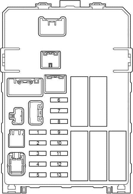
| Pozycja | Amperaż [A] | Chroniony obwód / funkcja |
|---|---|---|
| 1 | 15 | INJ – Multiport or sequential multiport fuel injection |
| 2 | 7.5 | OBD – On-board diagnostic system |
| 3 | 10 | STOP – Stop lamps, fuel injection, ABS, TRC, VSC and shift-lock control |
| 4 | 10 | TAIL – Instrument cluster, front fog lamps, headlamp levelling, front position lamps, rear and number plate lights, fuel injection, multi-information display, daytime running lights and automatic headlamp control |
| 5 | 15 | PWR OUT – Accessory power outlet |
| 6 | 7.5 | ST – Starting system, instrument cluster and fuel injection |
| 7 | 10 | A/C – Air-conditioning system |
| 8 | 7.5 | MET – Instruments, gauges and diesel particulate filter system |
| 9 | 15 | CIG – Cigarette lighter |
| 10 | 7.5 | ACC – Audio system, power outlet, clock, rear-view mirror controls, shift-lock system and information display |
| 11 | 7.5 | IGN – Fuel injection, SRS airbags and fuel pump |
| 12 | 20 | WIP – Windscreen wipers and washer |
| 13 | 10 | ECU-IG & GAUGE – Air conditioning, charging system, rear differential lock, ABS/TRC/VSC, hazard and turn signals, reversing lamps, fuel injection, shift lock, rear fog lamps, headlamps, door switches, central locking, remote keyless entry, steering angle sensor, daytime running lights, cruise control, seat heating, heated mirrors, information display and passenger seat-belt reminder |
Driver’s fuse panel – rear side and main feeds
AM1 and IG1 provide power to several smaller circuits. When several accessories fail at the same time, also check these upstream supplies, not just the individual small fuses.
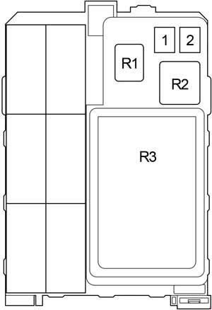
| Pozycja | Amperaż [A] | Chroniony obwód / funkcja |
|---|---|---|
| 1 | 40 | AM1 – Main supply for rear differential lock, ABS, TRC, VSC and the ACC, CIG, ECU-IG & GAUGE and WIP fuse circuits |
| 2 | 40 | IG1 – Supply for the PWR, S-HTR, 4WD, DOOR, DEF and MIR HTR fuses |
| Relays | ||
| R1 | – | Power outlet relay (PWR OUT) |
| R2 | – | Heater relay (HTR) |
| R3 | – | Integration relay |
Additional fuse and relay box behind glovebox – before June 2011
The earlier auxiliary carrier controls electric locks and windows, the heated rear window, optional seat heating and selected four-wheel-drive systems. Its ignition and demister relays are listed separately.
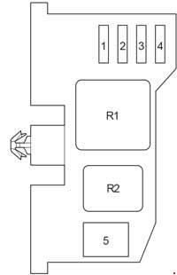
| Pozycja | Amperaż [A] | Chroniony obwód / funkcja |
|---|---|---|
| 1 | 25 | DOOR – Central locking and electric windows |
| 2 | 20 | DEF – Heated rear window and multiport or sequential multiport fuel injection |
| 3 | 15 | S-HTR – Heated seats |
| 4 | 20 | 4WD – Rear differential lock, ABS, TRC and VSC |
| 5 | 30 | PWR – Electric windows |
| Relays | ||
| R1 | – | Ignition relay (IG1) |
| R2 | – | Heated rear window relay (DEF) |
Additional fuse and relay box – from June 2011
The auxiliary carrier was revised in June 2011. Several positions were reassigned again in November 2011. Both chronological variants appear as separate rows below. Position 6 PWR is included from the later European Toyota handbook published for 2014.
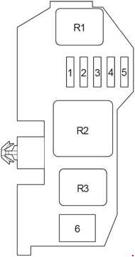
| Pozycja | Amperaż [A] | Chroniony obwód / funkcja |
|---|---|---|
| 1 | 15 | MIR HTR – Heated exterior mirrors, before November 2011 |
| 1 | 25 | DOOR – Central locking and electric windows, from November 2011 |
| 2 | 25 | DOOR – Central locking and electric windows, before November 2011 |
| 2 | 20 | DEF – Heated rear window and fuel injection, from November 2011 |
| 3 | 20 | DEF – Heated rear window and fuel injection, before November 2011 |
| 3 | 15 | S-HTR – Seat heaters, from November 2011 |
| 4 | 15 | S-HTR – Seat heaters, before November 2011 |
| 4 | 20 | 4WD – Rear differential lock, ABS, TRC and VSC, from November 2011 |
| 5 | 20 | 4WD – Rear differential lock, ABS, TRC and VSC, before November 2011 |
| 5 | 15 | MIR HTR – Heated exterior mirrors, from November 2011 |
| 6 | 30 | PWR – Electric windows, later European layout in the 2014 Toyota handbook |
| Relays | ||
| R1 | – | Exterior mirror heater relay (MIR HTR) |
| R2 | – | Ignition relay (IG1) |
| R3 | – | Heated rear window relay (DEF) |
Engine compartment fuse box and relay arrangements
This box covers the charging system, starter, ABS, headlamps, auxiliary heating and engine controls. Numbered fuse locations, alternative ratings and the additional relay-box assignments are retained together below. Headlamp, fog lamp, audio and heater fuse ratings can differ by build date and market.
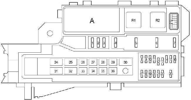
| Pozycja | Amperaż [A] | Chroniony obwód / funkcja |
|---|---|---|
| 1 | 25 | SPARE – Spare fuse |
| 2 | 15 | SPARE – Spare fuse |
| 3 | 10 | SPARE – Spare fuse |
| 4 | 7.5 | FOG – Front fog lamps for Europe and Morocco, August 2012 to August 2013 and from August 2013 |
| 4 | 15 | FOG – Front fog lamps before August 2013 in specified variants; outside Europe and Morocco, including August 2012 to August 2013 |
| 5 | 10 | HORN – Horn |
| 6 | 25 | EFI – Multiport or sequential multiport fuel injection |
| 7 | – | No circuit assignment given for this variant |
| 8 | 20 | H-LP RL – Right-hand dipped beam, before June 2011 |
| 8 | 15 | H-LP RL – Right-hand dipped beam, from June 2011 |
| 9 | 20 | H-LP LL – Left-hand dipped beam, before June 2011 |
| 9 | 15 | H-LP LL – Left-hand dipped beam, from June 2011 |
| 10 | 20 | H-LP RH – Right-hand main and dipped beams, before June 2011 |
| 10 | 15 | H-LP RH – Right-hand main and dipped beams, from June 2011 |
| 11 | 20 | H-LP LH – Left-hand main and dipped beams, before June 2011 |
| 11 | 15 | H-LP LH – Left-hand main and dipped beams, from June 2011 |
| 12 | 10 | EFI NO.2 – Multiport or sequential multiport fuel injection |
| 13 | 10 | ECU-IG NO.2 – Multiport or sequential multiport fuel injection |
| 14 | 7.5 | ECU-B – Door courtesy switches, power door locks, wireless remote control, control sensor and headlamps, before August 2008 |
| 14 | 10 | ECU-B – Door courtesy switches, power door locks, wireless remote control, control sensor and headlamps, from August 2008 |
| 15 | 15 | RAD – Audio system, before August 2013 |
| 15 | 20 | RAD – Audio system, from August 2013 |
| 16 | 7.5 | DOME – Interior lamps, ignition switch illumination, personal lamps, instruments, clock, multi-information display, remote control, daytime running lights and fog lamps |
| 17 | 20 | A/F – Emissions control system |
| 18 | 10 | ETCS – Engine fuel injection and electronic throttle control |
| 19 | 7.5 | ALT-S – Charging system |
| 20 | 15 | TURN-HAZ – Turn indicators and hazard warning lights |
| 21 | – | No circuit assignment given for this variant |
| 22 | 7.5 | ECU-B NO.2 – Air-conditioning system |
| 23 | 30 | DCC – Supply for ECU-B, DOME and RAD fuse circuits |
| 24 | 50 | PTC NO.1 – Electric auxiliary heater |
| 25 | 30 | H-LP CLN – Headlamp washers, before June 2011 |
| 25 | 30 | PWR SEAT – Electrically adjustable seat |
| 26 | 50 | PTC NO.2 – Electric auxiliary heater, Europe from August 2010 to June 2011 without automatic air conditioning, and from June 2011 |
| 26 | 30 | PTC NO.2 – Electric auxiliary heater, Europe before June 2011 with automatic air conditioning or before August 2010 without it; also Australian configurations |
| 27 | 40 | ABS NO.1 – ABS, TRC and VSC, before August 2008 |
| 27 | 40 | H-LP CLN – Headlamp washers, from June 2011 |
| 28 | 40 | FR HTR – Air-conditioning and A/C supply fuse, before August 2009 |
| 28 | 50 | FR HTR – Air-conditioning and A/C supply fuse, from August 2009 |
| 29 | 30 | ABS NO.2 – ABS, TRC and VSC |
| 30 | 40 | ABS NO.1 – ABS, TRC and VSC, from August 2008 |
| 31 | 100 | ALT – Charging system and upstream supply for PWR SEAT, H-LP CLN, FR HTR, AM1, IG1, PTC NO.1, PTC NO.2, PWR OUT, STOP, TAIL and OBD fuses |
| 32 | 80 | GLOW – Diesel glow plug system |
| 33 | 50 | BATT P/I – Supply for FOG, HORN and EFI fuses |
| 34 | 30 | AM2 – Engine starting and ST, IGN, INJ and MET fuse circuits |
| 35 | 40 | MAIN – Supply for H-LP RH, H-LP LH, H-LP RL and H-LP LL fuses |
| 36 | 50 | A/PUMP – Multiport or sequential multiport fuel injection |
| Main engine-bay relays | ||
| R1 | – | Dimmer relay (DIM) |
| R2 | – | Headlamp relay (H-LP) |
| Additional engine-bay relay box A | ||
| R1 | – | Starter relay (ST) |
| R2 | – | 1TR-FE, 2TR-FE, 1GR-FE: air-fuel ratio sensor (A/F); 1KD-FTV and 2KD-FTV without DPF, and 5L-E: glow system (GLOW). DPF-equipped 1KD-FTV and 2KD-FTV: air-fuel ratio sensor (A/F) |
| R3 | – | 1TR-FE, 2TR-FE, 1GR-FE: fuel pump relay (F/PMP); not assigned on the listed DPF-equipped 1KD-FTV and 2KD-FTV versions |
Year, engine and market differences
Before and after June 2011, both the additional glovebox panel and the headlamp fuse ratings can differ. November 2011 brought further position changes. A 15 A fuse must not be replaced by a 20 A fuse simply because another model-year chart shows the same slot number with a higher rating.
European, Moroccan and Australian specifications can also differ in the fog-lamp, auxiliary heater and optional-equipment circuits. Toyota’s European 2014 handbook describes an engine-box arrangement with some numbering differences from older versions. Select the diagram by engine code, market and build date, and confirm it against the actual cover label.
Electrical problems and the circuits worth checking
Dead 12 V outlet: Inspect PWR OUT (15 A), the power outlet relay and the socket contacts. CIG (15 A) is a separate circuit; failure of one outlet does not necessarily disable the other.
Wipers have stopped working: Check WIP (20 A) on the dashboard panel, followed by the wiper motor, stalk switch and wiring if the fuse is intact.
Electric windows or central locking fail: Check DOOR and PWR in the glovebox box as well as the IG1 feed. Their position numbering can differ after November 2011.
ABS, TRC or VSC warning lamps: ABS NO.1 and ABS NO.2 are in the engine compartment. If their fuses are sound, retrieve diagnostic trouble codes; a warning lamp does not establish that a fuse has failed.
Toyota IMV models and other Hilux generations
The Toyota Fortuner of the same period shares the Hilux’s IMV vehicle architecture, though its trim-dependent fuse occupancy can differ. The earlier Hilux VI has a different electrical installation. The eighth-generation Hilux, introduced from 2015, uses a revised distribution system; compare the generation carefully when a vehicle is registered in the crossover year.
Technical basis: Toyota Hilux VII owner handbooks, including European 2014 specifications, and the engine and market-specific fuse and relay layout drawings.