
The Mitsubishi Pajero IV, also marketed as Shogun (V80/V90, 2006-2015), has three fuse box groups: a passenger-compartment board and two separate engine-bay blocks. This guide preserves all 32 cabin positions, 30 fuses in engine compartment box A and three high-current positions in box B. The circuit assignments are based on Mitsubishi’s 2008 Pajero centralized junction documentation. Engines and equipment differ by year and market, so always check the actual fuse-box legend before replacing a fuse.
Where are the three Pajero IV fuse boxes?
Inside the cabin: Switch the ignition off, open the driver’s door and remove the lower dashboard fuse panel cover. The active fuse positions are numbered 1-28. The four spare fuses at positions 29-32 are stored in dedicated holders and are not connected to live circuits. Right-hand-drive Shogun variants may have another access orientation.
Engine compartment, box A: Open the bonnet and locate the main covered power-distribution block near the battery. Release the retaining catches, lift the cover and locate positions 1-30 using the drawing. This box includes fusible links for the alternator and major vehicle electrical feeds.
Engine compartment, box B: A separate smaller block provides positions 31-33 for ABS / braking and diesel glow-plug protection. Identify it using the third diagram and the physical lid, not the numbering on box A.
Passenger compartment – fuse positions 1-32
All numbered slots and spare fuse holders are included. In the 2008 service manual, cabin positions 4 (7.5 A) and 7 (30 A) have rated capacities but no specified load, so no circuit function has been invented for either position.
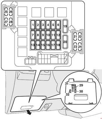
| Pozycja | Amperaż [A] | Chroniony obwód / funkcja |
|---|---|---|
| 1 | 10 | Ignition coil and engine management |
| 2 | 7.5 | Instrument cluster and body electronic modules |
| 3 | 7.5 | Reversing lamps and engine/transmission controllers |
| 4 | 7.5 | 7.5 A as specified in 2008 service documentation; load circuit not identified |
| 5 | 7.5 | Air-conditioning and passenger blower control relays |
| 6 | 7.5 | Heated exterior mirrors |
| 7 | 30 | 30 A as specified in 2008 service documentation; load circuit not identified |
| 8 | 7.5 | Engine management control |
| 9 | 15 | Cigarette lighter and 12 V accessory socket |
| 10 | – | Unused position |
| 11 | 7.5 | Electric exterior mirror adjustment |
| 12 | 7.5 | Engine, ABS, drivetrain and transmission electronics |
| 13 | – | Unused position |
| 14 | 15 | Rear window wiper and washer |
| 15 | 15 | Central door locking |
| 16 | 10 | Rear fog lamp |
| 17 | – | Unused position |
| 18 | – | Unused position |
| 19 | 30 | Passenger compartment blower motor |
| 20 | 30 | Heated rear window |
| 21 | 20 | Sunroof, where fitted |
| 22 | 10 | ABS and active stability/traction control (ASC / ASTC) |
| 23 | 20 | Heated seats, where fitted |
| 24 | 10 | Courtesy / approach lighting |
| 25 | 10 | Four-wheel-drive transfer case control |
| 26 | 10 | ENG/POWER – powertrain control supply |
| 27 | 10 | Starter control circuit |
| 28 | – | Unused position |
| 29 | 20 | Spare 20 A fuse on cover – not an active circuit |
| 30 | 10 | Spare 10 A fuse on cover – not an active circuit |
| 31 | 30 | Spare 30 A fuse on cover – not an active circuit |
| 32 | 25 | Spare 25 A fuse on cover – not an active circuit |
Main engine compartment fuse box A – positions 1-30
This box contains lighting, fuel pump, automatic transmission, air-conditioning and engine-management protection, as well as high-current fusible links. The main alternator circuit at position 1 is a 140 A fusible link, not a small blade fuse.
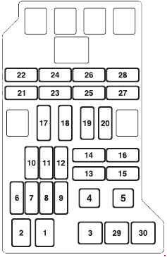
| Pozycja | Amperaż [A] | Chroniony obwód / funkcja |
|---|---|---|
| 1 | 140 | 140 A alternator main fusible link |
| 2 | 60 | Main +B electrical supply |
| 3 | 40 | Ignition switch, starter and control module supply |
| 4 | 30 | Power windows and front electrical module |
| 5 | 20 | Engine management, sensors and related components |
| 6 | 20 | Fuel pump |
| 7 | 25 | Rear passenger heater |
| 8 | 25 | 12 V accessory socket circuit |
| 9 | 25 | Diesel fuel-line heater |
| 10 | 25 | Air-conditioning condenser fan |
| 11 | 20 | Rear air-conditioning and heater blower, where fitted |
| 12 | 15 | 15 A position; protected load not identified in 2008 centralized junction service listing |
| 13 | 10 | Horn |
| 14 | 20 | Automatic transmission control |
| 15 | 10 | Turn signals and hazard warning lights |
| 16 | 15 | Brake / stop lamps |
| 17 | 10 | Radio and accessory audio equipment |
| 18 | 15 | Interior lighting and associated features |
| 19 | 10 | Air-conditioning control |
| 20 | 15 | Front fog lamps |
| 21 | – | Unused position |
| 22 | 20 | Front windscreen wipers and washers |
| 23 | 7.5 | Right-hand position and tail lamps |
| 24 | 7.5 | Left-hand position and tail lamps |
| 25 | 10 / 20 | Right dipped beam: 10 A for halogen headlamps, 20 A for discharge (HID) headlamps |
| 26 | 10 / 20 | Left dipped beam: 10 A for halogen headlamps, 20 A for discharge (HID) headlamps |
| 27 | 10 | Right-hand main-beam headlamp |
| 28 | 10 | Left-hand main-beam headlamp |
| 29 | 30 | Factory audio amplifier |
| 30 | 50 | Electric PTC supplementary heater |
Auxiliary engine compartment box B – positions 31-33
Positions 31 and 32 are the two main ABS / hydraulic brake power feeds. Position 33 protects the glow-plug supply on compatible diesel engines. These high-current fuses need the proper service procedure.
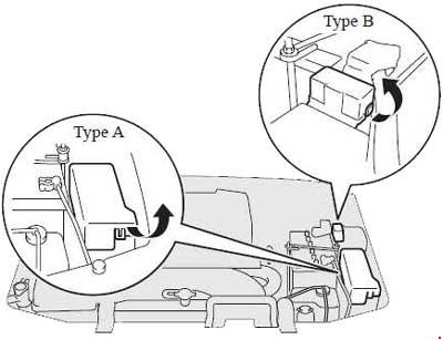
| Pozycja | Amperaż [A] | Chroniony obwód / funkcja |
|---|---|---|
| 31 | 60 | ABS and hydraulic braking booster, first high-current circuit |
| 32 | 40 | ABS / hydraulic braking system, second high-current circuit |
| 33 | 80 | Diesel glow plugs and glow plug control relay |
Halogen and discharge headlamp variations
Engine-bay fuses 25 and 26 protect the right and left dipped-beam circuits. Mitsubishi lists 10 A for halogen headlamps and 20 A for discharge (HID) headlamps. These values belong to different factory systems: fitting a higher-rated fuse on a halogen vehicle is not an upgrade. Optional equipment, including rear heating, powered seats, diesel fuel-line heating and four-wheel-drive electronics, also changes fuse occupancy.
Cigarette lighter, wipers, ABS and glow-plug faults
12 V power: Cabin fuse 9 (15 A) covers the cigarette lighter, while engine-bay box A position 8 (25 A) is associated with the additional accessory supply. Check which outlet has lost power before selecting a fuse.
Wipers and rear glass heating: Cabin fuse 14 (15 A) powers the rear wiper and washer, and cabin fuse 20 (30 A) the heated rear window. The front wiper circuit is protected by box A fuse 22 (20 A).
Braking and diesel starting: Cabin fuse 22 (10 A) feeds ABS / stability electronics. The additional high-current braking circuits are protected by box B fuses 31 (60 A) and 32 (40 A), while diesel glow plugs use position 33 (80 A). A recurrent fuse failure requires diagnosis of wiring or components rather than a higher amperage.
Pajero IV versus Mitsubishi L200 IV
The Mitsubishi L200 IV / Triton (2005-2015) was manufactured in a similar period but uses different fuse box numbering and electrical circuits. Use each model’s specific diagrams rather than assuming the positions are interchangeable.
Technical basis: Mitsubishi Motors Pajero 2008 electrical service documentation, “Centralized Junction”. These 2008 assignments should be confirmed against the actual fuse covers of other production years and markets.