
The facelifted Mazda CX-7 (2009-2012) uses a revised electrical layout with 36 numbered positions in the engine compartment fuse box and 19 in the driver’s cabin panel. The diagrams and ratings here follow the 2010 Mazda CX-7 owner’s manual. Vehicles built during the 2009 changeover, and especially models with the 2.2-litre diesel engine, should be checked against the fuse cover and documentation supplied with that specific vehicle.
Where are the Mazda CX-7 2009-2012 fuse boxes?
Under the bonnet: Switch the ignition off, raise the bonnet and locate the black fuse box beside the battery. Release the retaining clips and read the printed positions on the cover. The box includes high-current protection for vehicle electronics, cooling and engine supply circuits.
Inside the cabin: On left-hand-drive vehicles the fuse panel sits under the lower dashboard beside the driver’s footwell. Remove its small plastic access cover using the moulded catch. Right-hand-drive locations may be mirrored.
Note the paired OUTLET 1 and OUTLET 2 circuits, which protect different 12 V sockets. The independent P.SEAT (D) and P.SEAT (P) supplies refer to electrically adjustable driver and passenger seats. Check fitted options before assuming both positions are populated.
Engine compartment fuse box – positions 1-36
This is the post-facelift numbering. Blank or unspecified positions remain in the table, without assigning a guessed rating.
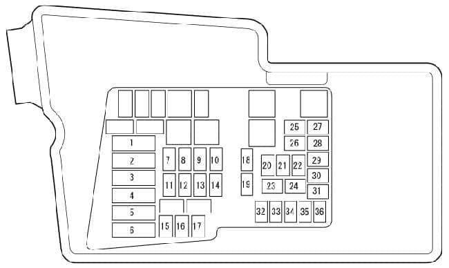
| Pozycja | Amperaż [A] | Chroniony obwód / funkcja |
|---|---|---|
| 1 | – | PCS – No fuse rating or assigned circuit specified in the 2010 layout |
| 2 | 40 | BLOWER – Heating and air-conditioning blower supply |
| 3 | 30 | FUEL PUMP – Fuel pump |
| 4 | 40 | FAN 2 – Auxiliary engine cooling fan |
| 5 | 40 | IG KEY 1 – Main ignition-switched power supply |
| 6 | 40 | FAN 1 – Main engine cooling fan |
| 7 | 30 | P.SEAT (D) – Electrically adjustable driver’s seat, where fitted |
| 8 | 30 | INJ 1 – Injector and engine management supply, depending on engine |
| 9 | 30 | P.SEAT (P) – Electrically adjustable passenger seat, where fitted |
| 10 | 30 | BOSE – Factory Bose sound system, where fitted |
| 11 | 30 | ENGINE – Engine management power supply |
| 12 | 20 | D.LOCK – Central door locking |
| 13 | 30 | P.WIND – Electric windows |
| 14 | 40 | IG KEY 2 – Second main ignition-switched power supply |
| 15 | 40 | ABS 1 – ABS, first supply circuit |
| 16 | 20 | ABS 2 – ABS, second supply circuit |
| 17 | – | DSC – Fuse rating not given for this variant |
| 18 | 20 | H/L CLEAN/ROOF – Electric sunroof or headlamp washers, depending on specification |
| 19 | 30 | DEF – Heated rear window |
| 20 | 15 | TNS – Position lamps, number-plate lamps and entry lighting |
| 21 | 10 | A/C – Air-conditioning system |
| 22 | 20 | TRAILER/TCM – Automatic transmission controller and optional equipment circuit, depending on variant |
| 23 | 15 | HEAD HI RH – Right-hand main-beam headlamp |
| 24 | 15 | HEAD HI LH – Left-hand main-beam headlamp |
| 25 | 15 | HEAD LO RH – Right-hand dipped-beam headlamp |
| 26 | 15 | HEAD LO LH – Left-hand dipped-beam headlamp |
| 27 | 10 | ETC – Electronic throttle and engine control, according to engine |
| 28 | 7.5 | ENG BAR 2 – Powertrain control supply |
| 29 | 10 | ECM – Engine management |
| 30 | 10 | INJ 2 – Second injection control circuit, according to version |
| 31 | 15 | ENG BAR 1 – Engine management including sensors and ancillary components |
| 32 | 15 | FOG – Front fog lamps, where fitted |
| 33 | 10 | STOP – Brake lamps |
| 34 | 20 | HORN – Horn |
| 35 | 25 | ENG B+ – Constant engine control unit supply |
| 36 | 10 | HAZARD – Turn indicators and hazard warning lights |
Cabin fuse panel – positions 1-19
The dashboard fuse arrangement differs from the 2006-2009 car. In particular, OUTLET 1 and OUTLET 2 are at positions 2 and 4 on this panel, rather than positions 1 and 2 on the earlier layout.
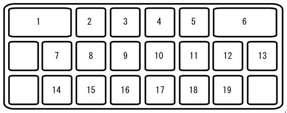
| Pozycja | Amperaż [A] | Chroniony obwód / funkcja |
|---|---|---|
| 1 | 30 | P.WIND 2 – Electric window controls |
| 2 | 15 | OUTLET 1 – First 12 V accessory power outlet |
| 3 | 7.5 | P.MIR – Electric exterior mirror adjustment |
| 4 | 15 | OUTLET 2 – Second 12 V accessory power outlet |
| 5 | – | SCR – No circuit assignment specified in this layout |
| 6 | 20 | WIPER – Front windscreen wipers and washers |
| 7 | 7.5 | M.DEF – Heated exterior mirrors, depending on equipment |
| 8 | 7.5 | P/ST/ENG BAR 3 – Powertrain and power steering electronics and engine accessories, depending on version |
| 9 | – | P.WIND – Fuse rating not specified for this variant |
| 10 | 7.5 | A/B – Advanced airbag system and seatbelt pretensioners |
| 11 | 15 | ENGINE – Engine management |
| 12 | 15 | METER – Instrument cluster |
| 13 | 10 | ILLUMI – Instrument panel illumination |
| 14 | 15 | ROOM – Interior lamps and audio system |
| 15 | – | R.FOG – Fuse rating not given in this listing |
| 16 | – | SIREN – Fuse rating not given in this listing |
| 17 | 20 | SEAT – Heated seats, where fitted |
| 18 | 10 | A/C – Air-conditioning system |
| 19 | 10 | R.WIP – Rear window wiper and washer |
Bose audio, powered seats, petrol and diesel engines
Equipment such as Bose audio, the sunroof, seat heaters and market-dependent lighting changes which fuses are used. Certain engine-management fuses, including INJ 1/2, ENGINE, ENG BAR 1/2/3 and ECM, serve separate circuits and should not be treated as substitutes. On diesel versions, confirm the correct fuel and engine electronics with the vehicle-specific cover legend.
Which fuse should you check first?
12 V outlets: Cabin positions 2 and 4 (OUTLET 1 and OUTLET 2, 15 A each) are separate. The fault can be limited to one socket or its wiring.
Wipers and seats: The rear wiper uses R.WIP (10 A) at cabin position 19. The front wipers use WIPER (20 A) at cabin position 6. If the driver’s powered seat is inoperative, inspect under-bonnet P.SEAT (D), position 7 (30 A).
Headlamps and brake lights: The dipped beams use separate HEAD LO RH and HEAD LO LH positions 25 and 26 (15 A each). Brake lamps use STOP, position 33 (10 A).
Engine management: Diagnostic trouble codes are required when investigating faults involving ECM, ENGINE, ENG BAR and INJ circuits. A failed component, wiring or ground connection can produce the same symptom as an open fuse.
Earlier Mazda CX-7 electrical layout
For cars produced before the facelift, refer to the separate Mazda CX-7 (2006-2009) fuse box guide. Its engine and cabin fuse positions are numbered differently, even where the circuit names appear similar.
Technical reference: Mazda CX-7 2010 owner’s manual, Maintenance and Care, “Fuse Panel Description”. Confirm build date, market and installed equipment against the specific vehicle.