
The European Ford Transit Mk6 (2000-2006) has a larger electrical distribution system than its predecessor, with 46 under-bonnet fuse positions, 27 dashboard fuses, relays and diodes. These tables cover the main and auxiliary relay blocks, including unused locations. Installation varies with 2.0 and 2.4 diesel engines, the 2.3 DOHC petrol engine, automated manual transmission, coachbuilt bodies and optional equipment.
Where are the Transit Mk6 fuse boxes?
Engine compartment: Switch off the ignition, open the bonnet and locate the main electrical box near the expansion tank and battery wiring. Release its lid clips and compare the printed position legend with the diagram. Certain versions also have an auxiliary relay carrier underneath the expansion tank or alongside the main box. The exact position varies with engine and vehicle body configuration.
Passenger compartment: The main fuse board is behind the drop-down trim or glovebox on the passenger side. Open the glovebox, carefully release the stops and lower the panel to expose fuse locations 201-227. Relays R14-R22 sit alongside the board. Use the access flap before attempting any larger dashboard disassembly.
Optional rear heating, air conditioning, powered windows, minibus equipment and trailer wiring can alter which relays are installed. Codes beginning Ra identify the auxiliary relay block, while D denotes a diode rather than a conventional relay.
Main engine compartment fuses – positions 1-24 and 101-122

| Pozycja | Amperaż [A] | Chroniony obwód / funkcja |
|---|---|---|
| 1 | 5 | Automated manual transmission, where fitted |
| 2 | – | Unused slot |
| 3 | 20 | Daytime running lights and dipped-beam headlights |
| 4 | 5 | Battery voltage sensor, diesel engines |
| 5 | 20 | Fuel cut-off switch |
| 6 | 30 | Towbar and trailer electrical supply |
| 7 | 15 | Horn |
| 8 | 20 | ABS system |
| 9 | 20 | Main-beam headlights |
| 10 | 10 | Air conditioning |
| 11 | 20 | Front and rear window washer pumps |
| 12 | – | Unused slot |
| 13 | 30 | Combination switch and front windscreen wipers |
| 14 | 15 | Reversing lamps |
| 15 | 5 | Engine immobiliser |
| 16 | 5 | Electronic engine management |
| 17 | 30 | Trailer wiring, second circuit |
| 18 | – | Unused slot |
| 19 | 5 | Automated manual transmission, where fitted |
| 20 | 15 | Automated manual transmission, where fitted |
| 21 | 20 | Engine control system |
| 22 | 20 | Fuel pump |
| 23 | 10 | Right-hand dipped-beam headlamp |
| 24 | 10 | Left-hand dipped-beam headlamp |
| 101 | 40 | Main ABS power supply |
| 102 | 40 | Left-hand heated windscreen circuit |
| 103 | 50 | Main electrical system supply |
| 104 | 50 | Second main electrical system supply |
| 105 | 40 | Cooling fan, 2.0-litre diesel and 2.3-litre DOHC petrol engines |
| 106 | 30 | Ignition switch power supply |
| 107 | 30 | Ignition switch power supply |
| 108 | – | Unused slot |
| 109 | 40 | Second cooling fan circuit, 2.0-litre diesel and 2.3-litre DOHC |
| 110 | 40 | Right-hand heated windscreen circuit |
| 111 | 30 | Ignition-switched power supply |
| 112 | – | Unused slot |
| 113 | 40 | Automated manual transmission, where fitted |
| 114 | – | Unused slot |
| 115 | – | Unused slot |
| 116 | – | Unused slot |
| 117 | – | Unused slot |
| 118 | – | Unused slot |
| 119 | – | Unused slot |
| 120 | – | Unused slot |
| 121 | – | Unused slot |
| 122 | – | Unused slot |
Under-bonnet relays R1-R13, Ra1-Ra6 and diodes D1-D4
The under-bonnet relay system can include more than one physical carrier. Some relay and diode positions are unused on specific engines. For example, relay R9 has different roles on TDdi and TDCi vehicles, and R2 can control either glow plugs or a cooling fan. A relay location is not assigned a blade-fuse amperage in this table.

| Pozycja | Amperaż [A] | Chroniony obwód / funkcja |
|---|---|---|
| R1 | – | Starter motor |
| R2 | – | Glow plugs or radiator fan, depending on engine |
| R3 | – | Horn |
| R4 | – | Main-beam headlamps |
| R5 | – | Alternator charge warning lamp and charging monitoring |
| R6 | – | Dipped-beam headlamps |
| R7 | – | Powertrain control module (PCM) |
| R8 | – | Bulb failure monitoring module, equipment dependent on ABS specification |
| R9 | – | Fuel pump on TDdi or injection module on TDCi, depending on engine |
| R10 | – | Air-conditioning control at full throttle, configuration dependent |
| R11 | – | Supply pump on certain TDdi variants |
| R12 | – | Radiator cooling fan |
| R13 | – | Main ignition-switched supply |
| Ra1 | – | Air compressor, where fitted |
| Ra2 | – | High-capacity cooling fan |
| Ra3 | – | Trailer left-hand turn indicators |
| Ra4 | – | Trailer right-hand turn indicators |
| Ra5 | – | Trailer electrical control |
| Ra6 | – | Unoccupied relay position |
| D1 | – | Diode location, function unspecified in this circuit variant |
| D2 | – | Diode location, function unspecified in this circuit variant |
| D3 | – | Trailer right indicator or air-conditioning clutch, depending on installation |
| D4 | – | Trailer left indicator or air-conditioning signalling, depending on installation |
Passenger-compartment fuse panel – positions 201-227
The passenger board serves lighting, cabin blowers, sockets, radio, wipers and heated windows. Fuse 212 supplies the lighter, while 216 protects an additional accessory socket; these are independent feeds.
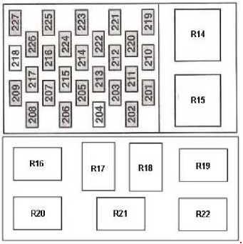
| Pozycja | Amperaż [A] | Chroniony obwód / funkcja |
|---|---|---|
| 201 | 15 | Instrument cluster, rear wiper and clock |
| 202 | 5 | Heated windscreen control |
| 203 | 20 | Front fog lamps |
| 204 | – | Unused slot |
| 205 | 15 | Lighting controls, turn signals, combination switch and engine control |
| 206 | 5 | Number-plate lighting |
| 207 | 10 | SRS airbag controller |
| 208 | 10 | Instrument illumination |
| 209 | 15 | Position lamps |
| 210 | 15 | Tachograph or clock, depending on specification |
| 211 | 30 | Rear compartment heater blower |
| 212 | 10 | 12 V cigarette lighter |
| 213 | 10 | Rear air conditioning |
| 214 | 15 | Interior lights and electric mirrors |
| 215 | 20 | Heated windscreen, seats and auxiliary heating, depending on variant |
| 216 | 20 | Additional 12 V accessory socket |
| 217 | 15 | Heated rear window and exterior mirrors |
| 218 | – | Unused slot |
| 219 | 30 | Electric windows |
| 220 | 20 | Additional heated rear window circuit |
| 221 | 15 | Brake-light switch |
| 222 | 15 | Radio |
| 223 | 30 | Front heater blower |
| 224 | 20 | Exterior lighting master switch |
| 225 | 15 | Air-conditioning control |
| 226 | 20 | Turn signals and hazard warning lights |
| 227 | 5 | Radio and ABS circuit |
Passenger-compartment relays – R14 to R22
These relays are fitted according to vehicle body, auxiliary heating and window equipment. The separate diagram also shows an alternative relay arrangement on selected vehicles.
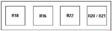
| Pozycja | Amperaż [A] | Chroniony obwód / funkcja |
|---|---|---|
| R14 | – | Front windscreen wipers |
| R15 | – | Battery-saving relay, engine running D+ signal |
| R16 | – | Right-hand heated windscreen |
| R17 | – | Rear or sliding door warning circuit, according to body style |
| R18 | – | Interior lighting |
| R19 | – | Rear door ajar warning, vehicle wiring variant |
| R20 | – | Left-hand heated windscreen |
| R21 | – | Rear window wiper |
| R22 | – | Heated rear window and exterior mirrors |
Cigarette lighter, fuel pump, wipers and heated windscreen
12 V power outlets: A dead cigarette lighter points to passenger fuse 212 (10 A); a separate outlet is protected by passenger fuse 216 (20 A). Verify the actual socket contacts before replacing other components.
Starting and fuel supply: Engine-bay fuse 22 (20 A) is associated with the fuel pump. Check the corresponding relay and engine management circuits, taking account of differences between TDdi and TDCi diesel injection equipment.
Front wipers: Inspect engine-bay fuse 13 (30 A), cabin relay R14 and the combination switch. In a car with a heated windscreen, the left and right halves are protected separately by high-current fuses 102 and 110 (40 A each).
Headlamps: Right-hand and left-hand dipped beams have separate under-bonnet fuses 23 and 24, both 10 A. Central-locking and alarm-equipped conversions may have additional fuses behind the instrument cluster, depending on the body configuration.
Transition from Transit Mk5 and the 2006 redesign
Transit Mk5 (1995-2000) has a different single dashboard panel and numbering system. Its fuse and relay guide is the appropriate reference for the earlier “Smiley” vehicle. The first 2000 model year can also have a specific European equipment listing. Following the 2006 generation change, Transit fuse carriers were redesigned again, so the Mk6 layout should not be used automatically on later vehicles.
Technical basis: Ford Transit owner documentation for vehicles built from January 2000 to May 2006 and European fuse and relay layouts. Check the engine code, equipment and fuse-cover legend before replacing a fuse.