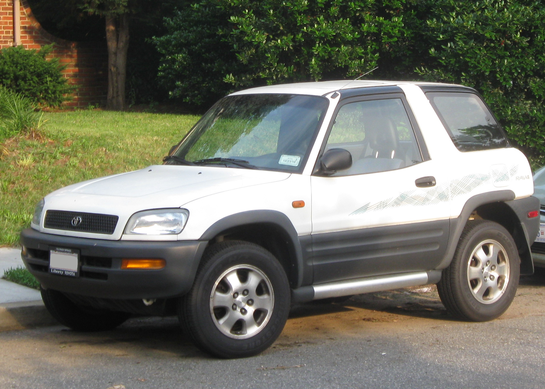
The first-generation Toyota RAV4 (XA10, SXA10/SXA11, 1994-1997) has multiple fuse and relay carriers inside the engine bay and beneath the dashboard. The six separate layouts below include main fuses, auxiliary relays and two additional interior modules. Equipment differs by market and production year, so identify the physical box before using its position numbers. A label such as R1 is reused in more than one relay box.
Where are the fuse boxes and how do you open them?
Under the bonnet: Switch the ignition off and open the bonnet. Locate the fuse box at the side of the engine compartment; separate relay and high-current supply components are nearby. Release the plastic cover clips carefully, especially on older vehicles where the retaining tabs may have become brittle. Compare the printed diagram with the actual panel.
Inside the vehicle: In left-hand-drive cars, open the driver’s door and look under the dashboard near the driver’s feet. Undo the lower protective trim to expose the main fuse board. Additional relay modules sit farther behind the trim and can require another access panel. Right-hand-drive models can have a different orientation.
Some markets also use a separate high-current fusible-link carrier. Do not assume its numbering is identical to that of the standard 1-20 engine compartment fuse box without the correct vehicle diagram.
Engine compartment fuse box – fuses 1-20 and relays R1-R3
This diagram covers the main EFI, AM2, headlamp, horn/hazard and cooling-fan circuits. Every unused position remains listed rather than being dropped from the table.

| Pozycja | Amperaż [A] | Chroniony obwód / funkcja |
|---|---|---|
| 1 | – | Unassigned |
| 2 | – | Unassigned |
| 3 | 15 | H-LP LH – Left headlamp |
| 4 | 15 | H-LP RH – Right headlamp |
| 5 | – | Unassigned |
| 6 | – | Unassigned |
| 7 | 15 | SPARE – Replacement fuse |
| 8 | 10 | SPARE – Replacement fuse |
| 9 | 5 | ALT-S – Charging system |
| 10 | – | Unassigned |
| 11 | 15 | HAZ-HORN – Hazard warning lights and horn |
| 12 | 15 | EFI – Multiport or sequential fuel injection system |
| 13 | 15 | DOME – Interior lamps, open-door warning and clock |
| 14 | 20 | AM2 – Fuel injection and charging system |
| 15 | 30 | CDS FAN – Electric engine cooling fan |
| 16 | 30 | RDI FAN – Electric engine cooling fan |
| 17 | – | Unassigned |
| 18 | 30 | MAIN No. 1 – Starting system and headlamps |
| 19 | 60 | ABS – Anti-lock braking system on equipped versions through 1997 |
| 20 | – | Unassigned |
| R1 | – | Main power relay |
| R2 | – | Headlamp relay |
| R3 | – | Starter relay |
Additional engine compartment relay carrier
This separate block controls EFI, cooling fan circuits, horn and air-conditioning compressor clutch. Its R1-R6 labels are independent of the first fuse box.
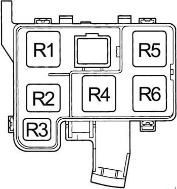
| Pozycja | Amperaż [A] | Chroniony obwód / funkcja |
|---|---|---|
| R1 | – | EFI main relay |
| R2 | – | Cooling fan relay No. 1 |
| R3 | – | Horn relay |
| R4 | – | Cooling fan relay No. 3 |
| R5 | – | Air-conditioning compressor clutch relay |
| R6 | – | Cooling fan relay No. 2 |
Primary passenger compartment fuse box
These positions protect interior accessories, dashboard electronics, the wipers and the charging and engine-management control feeds. The Toyota 1996 handbook specifies GAUGE at 10 A, not 11 A.
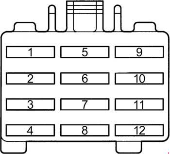
| Pozycja | Amperaż [A] | Chroniony obwód / funkcja |
|---|---|---|
| 1 | 10 | TAIL – Tail, parking and registration plate lamps plus interior lighting |
| 2 | 10 | GAUGE – Gauges, warning indicators, reverse lights, A/C, windows, rear demister, centre differential lock and automatic transmission |
| 3 | 7.5 | TURN – Indicators |
| 4 | 15 | CIG & RAD – Cigarette lighter, clock, audio system and electric mirrors |
| 5 | 7.5 | DEF-I/UP – Fuel injection control |
| 6 | 7.5 | IGN – Fuel injection system and battery charge warning |
| 7 | 7.5 | ECU-IG – ABS and electronically controlled automatic gearbox |
| 8 | 20 | WIPER – Front and rear wipers and washers |
| 9 | – | Unassigned |
| 10 | 7.5 | SRS – Airbag system |
| 11 | 7.5 | OBD – On-board diagnostics |
| 12 | 10 | STOP – Brake lights |
Separate cabin relay panel
The circuit opening relay marked R1 in this box is not the engine-compartment main relay. Always identify the correct drawing before moving a relay.
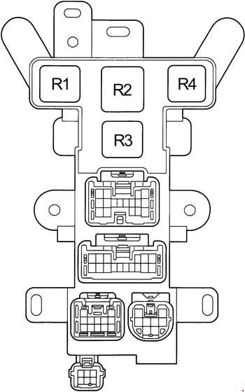
| Pozycja | Amperaż [A] | Chroniony obwód / funkcja |
|---|---|---|
| R1 | – | Circuit opening relay |
| R2 | – | Unassigned relay position |
| R3 | – | Turn signal flasher relay |
| R4 | – | Unassigned relay position |
Additional interior fuse and relay box No. 2
The auxiliary board contains the POWER electric-window circuit, rear demister, main AM1 supply, noise filter and supporting relays.
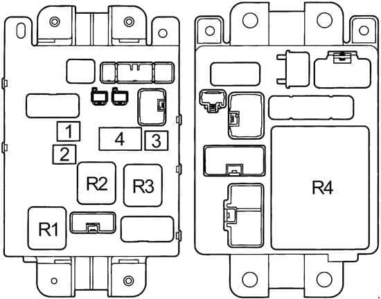
| Pozycja | Amperaż [A] | Chroniony obwód / funkcja |
|---|---|---|
| 1 | 30 | POWER – Electric windows and central locking |
| 2 | 30 | DEF – Heated rear window |
| 3 | 40 | AM1 – Supply for CIG & RAD, WIPER, GAUGE, ECU-IG, TURN, TAIL and PANEL fuses |
| 4 | – | Electrical noise suppression filter – not a fuse |
| R1 | – | Rear-window demister relay |
| R2 | – | Main power relay |
| R3 | – | Tail lamp relay |
| R4 | – | Integration relay |
Additional interior fuse and relay box No. 3
A smaller module carries the air-conditioning fuse and the heater relay, plus an unassigned position.
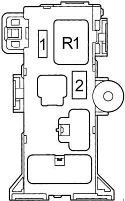
| Pozycja | Amperaż [A] | Chroniony obwód / funkcja |
|---|---|---|
| 1 | 7.5 | A/C – Air-conditioning system |
| 2 | – | Unassigned |
| R1 | – | Heater relay |
Diagnosing common electrical faults
Lighter and radio: Check CIG & RAD (15 A) in the main interior panel if both lose power. Wipers: WIPER (20 A) covers the front and rear wipers and washers. Dashboard instruments: GAUGE (10 A) is relevant if gauges, reverse lighting or related controllers fail.
Cooling: CDS FAN and RDI FAN each use 30 A in this installation and have separate relays. Engine starting: EFI (15 A), AM2 (20 A) and the engine control relays are worth checking alongside battery voltage and wiring. A fuse which repeatedly blows requires a circuit fault diagnosis, not a higher replacement rating.
Toyota RAV4 after 2000
The later Toyota RAV4 II XA20 (2000-2005) has different fuse numbering and electrical equipment. Its fuse boxes are not interchangeable with the XA10 installation shown here.
Reference: 1996 Toyota RAV4 owner’s manual and 1994-1997 XA10 diagrams. Always verify engine, market and production year against the label on the installed box.