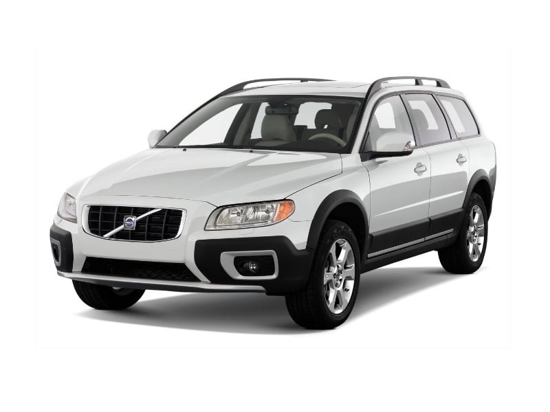
Volvo XC70 II and V70 III (2007-2016) share Volvo’s P3 electrical architecture, but their fuse assignments changed between early and later production. The V70 is the standard estate, whereas the XC70 has raised ground clearance and is frequently equipped with all-wheel drive. Most cars were sold as model year 2008 onward; 2011 is a transition year in which either fuse layout may be found.
This comprehensive English guide contains all 217 original positions across 12 tables, covering the engine compartment, fuse boxes A and B beneath the glovebox, the luggage compartment, cold-zone Start/Stop power and relays. Ratings and equipment can differ by year, engine, market and option. Never replace a fuse with a higher rating based on another model’s diagram.
Where are the XC70 II and V70 III fuse boxes?
Depending on build year and equipment, the car can have the main engine-bay box near the battery, two fuse units A and B beneath the passenger glovebox, a fuse and relay block behind the left luggage-compartment side trim, and a supplementary high-current cold-zone box on Start/Stop versions. On right-hand-drive vehicles the positions of the under-dash units are mirrored.
The earlier Volvo XC70 P2 (2003-2006) has a different electrical platform. Its diagrams and fuse numbers must not be reused on the P3 XC70. For another early Volvo SUV of a separate generation, see the Volvo XC90 I (2004) fuse guide; the Volvo C70 II (2010-2013) likewise uses a different fuse layout despite shared Volvo branding.
Most commonly checked XC70 / V70 fuses
Positions below are linked to the correct year range and fuse box. Fuse box A was reorganised around model year 2011, so an actual fuse-cover diagram is more reliable than the registration year alone.
| Component | Model years | Fuse position / rating | Fuse box |
|---|---|---|---|
| Front cigarette lighter / 12 V socket | 2007-2010 | 25 – 15 A | Engine compartment |
| 12 V socket in tunnel console | 2011-2016 | 22 – 15 A | Box A under glovebox |
| Luggage compartment 12 V outlet | 2007-2010 | Section 1, position 6 – 15 A | Luggage compartment |
| Luggage compartment 12 V outlet | 2011-2016 | 7 – 15 A | Box A under glovebox |
| Front windscreen wipers | All years | 9 – 30 A | Engine compartment |
| Rear window wiper | 2007-2011 | 20 – 15 A | Box B, early layout |
| Rear window wiper | 2011-2016 | 1 – 15 A | Box B, later layout |
| Fuel pump | 2007-2011 | 22 – 20 A | Box B, early layout |
| Fuel pump | 2011-2016 | 13 – 20 A | Box B, later layout |
| Horn | All years | 29 – 15 A | Engine compartment |
| Heating and ventilation blower | All years | 11 – 40 A | Engine compartment |
| Heated rear window | 2007-2010 | Section 1, position 7 – 30 A | Luggage compartment |
| Heated rear window | 2011-2016 | 3 – 30 A | Luggage compartment |
| Heated front seats | 2012-2016 | 26 and 27 – each 15 A | Box A under glovebox |
| Electric parking brake | 2011-2016 | 1 and 2 – each 30 A | Luggage compartment |
| All-wheel-drive (AWD) system | 2011-2012 | 29 – 10 A | Box A under glovebox |
| All-wheel-drive (AWD) system | 2013-2016 | 29 – 15 A | Box A under glovebox |
| ABS pump | All years | 13 – 40 A | Engine compartment |
Electrical changes: 2007-2010, 2011, 2012-2013 and 2014-2016
2011 is the transitional period: the same car name can have the earlier CEM box or later boxes A and B. From 2012 onward Sensus, the heated windscreen, AWD options, Start/Stop and Drive-E engines further changed fuse population. The following year-based table does not mean every option is standard.
| Years | Electrical layout |
|---|---|
| 2007-2010 | 2007-2010: Early Central Electronic Module (CEM) box under the glovebox. Some door, seat, AWD and audio protection is in the three-section luggage compartment panel; the center-console socket is on engine-bay fuse 25 |
| 2011 | 2011: Transitional model year. The earlier or later box arrangement may apply, so compare the printed cover and physical panel |
| 2012-2013 | 2012-2013: Later CEM fuse box and revised positions for heated seats, Sensus infotainment, 12 V sockets and AWD; certain cars add Start/Stop |
| 2014-2016 | 2014-2016: Later layout may include heated steering wheel, heated windscreen, Start/Stop auxiliary battery and four-cylinder Drive-E engines |
Under-glovebox fuse box A (mainly 2011-2016)
Box A contains audio, front and rear door control modules, heated seats, optional Keyless, power seats, 12 V outlets, AWD and Four-C suspension protection. It has 30 numbered positions. The table separates 2011-2013 from 2014-2016 functions, including the switch in seat-heating positions and the AWD controller rating (10 A on 2011-2012 variants, 15 A on later versions).
| Position | 2011-2013 | 2014-2016 |
|---|---|---|
| 1 | 40 A: main audio-control supply and fuses 16-20 | 40 A: main audio-control fuse and positions 16-20 |
| 2 | Unused | Unused in base layout |
| 3 | Unused | Unused |
| 4 | Unused on most versions | 10 A: heated steering wheel |
| 5 | Unused | Unused |
| 6 | Unused | Unused |
| 7 | 15 A: luggage compartment 12 V socket | 15 A: luggage compartment 12 V outlet |
| 8 | 20 A: driver door control module | 20 A: driver door control module |
| 9 | 20 A: passenger front door control module | 20 A: front passenger door control module |
| 10 | 20 A: right rear door control module | 20 A: right rear door control module |
| 11 | 20 A: left rear door control module | 20 A: left rear door control module |
| 12 | 20 A: Keyless entry | 20 A: Keyless |
| 13 | 20 A: driver power seat | 20 A: driver power seat |
| 14 | 20 A: passenger power seat | 20 A: passenger power seat |
| 15 | 15 A: folding rear headrests in 2011-2012; normally unused in 2013 | Unused |
| 16 | 5 A: infotainment module or display from 2012 | 5 A: infotainment controller or display |
| 17 | 10 A: audio amplifier, TV or digital radio | 10 A: amplifier, TV or digital radio |
| 18 | 15 A: audio module or Sensus controller | 15 A: audio or Sensus module |
| 19 | 5 A: telematics and Bluetooth | 5 A: telematics and Bluetooth |
| 20 | Unused | 7.5 A: optional rear-seat multimedia system, otherwise unused |
| 21 | 5 A: sunroof, overhead lighting and climate sensor | 5 A: sunroof, roof lighting, climate sensor and air-flap actuators |
| 22 | 15 A: center-console 12 V socket / cigarette lighter | 15 A: 12 V socket in the tunnel console |
| 23 | 2011: 15 A passenger heated seat; 2012-2013: right rear heated seat | 15 A: right rear heated seat |
| 24 | 2011: 15 A driver heated seat; 2012-2013: left rear heated seat | 15 A: left rear heated seat |
| 25 | Unused | Unused |
| 26 | 2011: 15 A right rear heated seat; 2012-2013: front passenger heated seat | 15 A: passenger seat heating or ventilation |
| 27 | 2011: 15 A left rear heated seat; 2012-2013: driver heated seat | 15 A: driver seat heating or ventilation |
| 28 | 5 A: parking sensors, reversing camera and BLIS | 5 A: parking sensors, camera and towbar module |
| 29* | 2011-2012: 10 A AWD module; 2013: 15 A AWD module | 15 A: AWD control module |
| 30 | 10 A: Four-C active chassis | 10 A: Four-C active chassis |
Cigarette lighter / center-console 12 V socket: box A position 22 (15 A) on later models. Cargo socket: A7 (15 A), if fitted. Heated seat fuses 23/24 and 26/27 vary with year, so do not exchange them blindly.
Early fuse box B / CEM under the glovebox (2007-2011)
The early unit has 28 positions, with the rear wiper at 20 (15 A), fuel pump at 22 (20 A), and brake light switch at 28 (5 A). It also supplies ACC, SRS, steering lock, front fog lamps and the 2007-2011 washer controls.
| Position | Rating [A] | Protected circuit / function |
|---|---|---|
| 1 | 5 | Rain sensor |
| 2 | 10 | SRS airbags |
| 3 | 5 | ABS electronics |
| 4 | 7.5 | Accelerator pedal sensor, auxiliary heater and heated seats |
| 5 | – | Unused position |
| 6 | 15 | ICM display, CD player, radio and rear entertainment |
| 7 | 7.5 | Steering wheel module |
| 8 | – | Unused position |
| 9 | 15 | High-beam headlamps and high-beam warning |
| 10 | 20 | Sunroof |
| 11 | 7.5 | Reversing lamps |
| 12 | – | Unused position |
| 13 | 15 | Front fog lamps |
| 14 | 15 | Front windscreen washer pump |
| 15 | 10 | Adaptive cruise control (ACC) |
| 16 | – | Unused position |
| 17 | 7.5 | Cabin and door panel lighting and power-window control |
| 18 | 5 | Information display |
| 19 | 5 | Power driver seat control |
| 20 | 15 | Rear window wiper |
| 21 | 5 | Remote key receiver and alarm sensors |
| 22 | 20 | Fuel pump |
| 23 | 20 | Electric steering column lock |
| 24 | – | Unused position |
| 25 | 10 | Fuel filler flap and tailgate locking |
| 26 | 5 | Alarm siren and electronic climate control (ECC) |
| 27 | 5 | Start/Stop button or Keyless start |
| 28 | 5 | Brake-light switch |
Later fuse box B / CEM under the glovebox (2011-2016)
This revised unit contains 24 positions: rear wiper 1 (15 A), fuel pump 13 (20 A), front washer 10 (15 A) in the early version of this layout, and diagnostic/alarm electronics. Positions 9 and 10 can change function on cars with heated windscreen or steering wheel; use the actual panel chart.
| Position | Rating [A] | Protected circuit / function |
|---|---|---|
| 1 | 15 | Rear window wiper |
| 2 | – | Unused position |
| 3 | 7.5 | Interior lighting, driver door power windows and electric seats |
| 4 | 5 | Instrument cluster |
| 5 | 10 | Adaptive cruise control (ACC) and collision warning |
| 6 | 7.5 | Interior lighting, rain sensor and HomeLink |
| 7 | 7.5 | Steering wheel module |
| 8 | 10 | Central locking and fuel filler flap lock |
| 9* | 15 | 2011-2013: rear washer; selected 2014-2016: heated steering wheel control |
| 10* | 15 | 2011-2013: front windscreen washer; some later layouts use heated-screen control |
| 11 | 10 | Tailgate release |
| 12 | 10 | 2011: tailgate lock; 2012: unused; 2013-2016: folding rear headrests |
| 13 | 20 | Fuel pump |
| 14 | 5 | Alarm movement sensor and climate panel |
| 15 | 15 | Electric steering column lock |
| 16 | 5 | Alarm siren and OBD diagnostics |
| 17 | – | Unused or market-specific audio equipment |
| 18 | 10 | SRS airbags and front passenger presence sensor |
| 19 | 5 | Collision warning system |
| 20 | 7.5 | Accelerator pedal sensor, electrochromic mirror, heated rear seats and auxiliary cabin heater |
| 21 | 15 | Basic infotainment unit on equipped cars, otherwise unused |
| 22 | 5 | Brake lights |
| 23 | 20 | Panoramic or ordinary electric sunroof |
| 24 | 5 | Immobiliser and engine-start lock |
Engine compartment fuses and relays 1-44
The engine compartment unit includes upper section A, front section B and lower section C. It protects the CEM and other electrical modules, engine and gearbox controllers, ABS, headlamps, air conditioning, cooling, starter and parking heater. Front wipers: position 9 (30 A). Horn: position 29 (15 A). Cabin blower: position 11 (40 A). ABS pump: position 13 (40 A); valves position 14 (20 A).
| Position | Rating [A] | Protected circuit / function |
|---|---|---|
| 1 | 50 | Main feed to the Central Electronic Module (CEM) under the glovebox |
| 2 | 50 | Second main CEM power feed under the glovebox |
| 3 | 60 | Main rear cargo electrical unit power feed |
| 4 | 60 | Main power supply for fuse box A under the glovebox |
| 5* | 50 or 60 | Second feed for fuse box A, rating depends on model year |
| 6 | – | Unused position |
| 7 | 100 | Optional PTC electric air preheater |
| 8* | 20 or 40 | Headlamp washers or left heated windscreen circuit, depending on year and market |
| 9 | 30 | Front windscreen wiper motor and relay |
| 10 | 25 | Optional parking heater |
| 11 | 40 | Heating and climate-control blower motor |
| 12* | 40 or – | Right heated windscreen circuit or unused position |
| 13 | 40 | ABS hydraulic pump |
| 14 | 20 | ABS hydraulic valves |
| 15* | 20 or – | Headlamp washers on later versions, otherwise unused |
| 16 | 10 | Headlamp levelling and Active Bending Lights (ABL) |
| 17 | 20 | Main CEM supply under the glovebox |
| 18 | 5 | 2008-2010: adaptive cruise control radar; 2011 onward: ABS electronics |
| 19 | 5 | Speed-sensitive power steering |
| 20 | 10 | ECM, automatic transmission controller and SRS system |
| 21 | 10 | Heated windscreen washer nozzles |
| 22 | – | Unused position |
| 23 | 5 | Headlamp lighting control panel |
| 24* | 15 or – | Early versions: headlamp washers; usually unused later |
| 25* | 15 or – | 2007-2010: front and rear console 12 V outlets; unused later |
| 26* | 5 or – | 2007-2010: sunroof and overhead console; unused later |
| 27 | 5 | Engine box or washer relay coils |
| 28 | 20 | Auxiliary driving lamps |
| 29 | 15 | Horn |
| 30* | 5 or 10 | ECM and main engine-management relay coil |
| 31 | 15 | Automatic transmission control module |
| 32* | 15 | Air-conditioning compressor clutch or electric coolant pump by engine |
| 33 | 5 | A/C, coolant pump or Start/Stop relay coils |
| 34 | 30 | Starter relay on vehicles without Start/Stop |
| 35* | 10 or 20 | Ignition coils, ECM or diesel glow plug controller, engine-specific |
| 36* | 10, 15 or 20 | Petrol or diesel ECM, varies by cylinder count and year |
| 37* | 10 or 15 | Mass airflow meter, thermostat, EVAP valve, fuel injection and ECM |
| 38* | 10 or 15 | A/C compressor, engine valves, oil pump, oxygen sensors and oil level sensor |
| 39* | 10 or 15 | Oxygen sensors, EVAP, injection system and radiator grille shutter control |
| 40* | 10, 15 or 20 | Vacuum pump, ignition coils, fuel filter heater or breather heater |
| 41* | 5, 10 or 15 | Crankcase ventilation heater, gearbox oil pump, A/C clutch, glow plug controller or grille shutter |
| 42* | 50 or 70 | Diesel glow plugs or four-cylinder engine coolant pump, depending on version |
| 43* | 60 or 80 | Radiator cooling fan, ampere rating depends on engine |
| 44* | 80 or 100 | Power steering supply; on some early cars a cooling fan supply |
Variable fuse ratings: positions 5, 8, 12, 15, 18, 24-26 and many engine-specific positions 30-44 depend on motorisation, model year or optional heated windscreen. Some P3 Volvo modules look alike across the XC60 and S80, but identical housings do not establish identical XC70 assignments; only XC70/V70 manufacturer data and your vehicle’s fuse lid should be used for replacement choices.
Cold-zone fuse box on Start/Stop models
Selected models have additional MEGA and MIDI high-current protection. A1 and A2 (175 A each) feed the engine and the interior/cargo electrical units. The optional PTC heater, CEM, fan, starter and auxiliary battery are also separately protected. The main MEGA/MIDI fuses are intended for workshop diagnosis and replacement.
| Position | Rating [A] | Protected circuit / function |
|---|---|---|
| A1 | 175 | Main engine-compartment electrical power distribution |
| A2 | 175 | Main feeds for under-glovebox fuse boxes and rear electrical module |
| 1* | 100 or – | Optional PTC electric heater, by engine and market |
| 2 | 50 | Main CEM supply beneath glovebox |
| 3 | 60 | Main feed for passenger fuse box A |
| 4* | 60 | Secondary box A supply or heated windscreen, depending on build |
| 5 | 60 | Main cargo fuse-box supply |
| 6 | 40 | Heating and ventilation blower |
| 7 | – | Unused position |
| 8 | – | Unused position |
| 9 | 30 | Starter relay |
| 10* | 50 or – | Internal diode, dependent on the electrical module version |
| 11 | 70 | Auxiliary battery |
| 12* | 5 or 15 | CEM reference voltage and auxiliary battery charging point |
Early 2007-2010 cargo fuse box: three sections
Behind the left boot trim, earlier V70/XC70 cars can have a three-section relay/fuse assembly. Several consumers later moved to the glovebox-area unit. These are three independent 1-12 position groups, not one 36-position numbering sequence.
Early cargo section 1
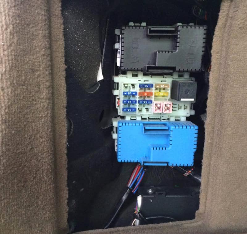
| Position | Rating [A] | Protected circuit / function |
|---|---|---|
| 1 | 25 | Driver door control panel |
| 2 | 25 | Front passenger door control panel |
| 3 | 25 | Left rear door electronics |
| 4 | 25 | Right rear door electronics |
| 5 | – | Unused position |
| 6 | 15 | Cargo area 12 V socket |
| 7 | 30 | Heated rear window |
| 8 | – | Unused position |
| 9 | 15 | Secondary trailer wiring feed |
| 10 | 25 | Power driver seat |
| 11 | 40 | Main trailer wiring power |
| 12 | 30 | Power-operated tailgate |
Early cargo section 2
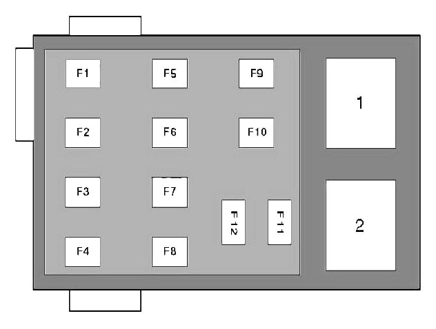
| Position | Rating [A] | Protected circuit / function |
|---|---|---|
| 1 | 5 | Parking sensors and reversing camera |
| 2 | 15 | Four-C active chassis control module |
| 3 | 15 | Driver heated front seat |
| 4 | 15 | Front passenger heated seat |
| 5 | 15 | Right rear heated seat |
| 6 | 10 | AWD control module |
| 7 | 15 | Left rear heated seat |
| 8 | – | Unused position |
| 9 | 25 | Electric passenger seat |
| 10 | 20 | Keyless entry system |
| 11 | 30 | Left electric parking brake |
| 12 | 30 | Right electric parking brake |
Early cargo section 3
| Position | Rating [A] | Protected circuit / function |
|---|---|---|
| 1 | 10 | RTI navigation display |
| 2 | – | Unused position |
| 3 | 25 | Subwoofer circuit |
| 4 | 5 | DAB digital radio |
| 5 | 25 | Factory audio amplifier |
| 6 | 15 | Factory audio system |
| 7 | 5 | Phone and Bluetooth |
| 8 | – | Unused position |
| 9 | – | Unused position |
| 10 | – | Unused position |
| 11 | – | Unused position |
| 12 | – | Unused position |
On the early rear panel, section 1 position 6 (15 A) protects the luggage 12 V socket, and section 1 position 7 (30 A) the heated rear window. AWD can be protected by section 2 position 6 (10 A). Pay close attention to the section number before removing a fuse.
Later 2011-2016 luggage-compartment fuse box
The newer panel has 12 positions. Electric parking brake: 1 and 2 (30 A each). Heated rear window: 3 (30 A). Electric tailgate: 5 (20 A in this later table). Some seat, audio and AWD feeds were moved to box A under the glovebox.
| Position | Rating [A] | Protected circuit / function |
|---|---|---|
| 1 | 30 | Left electric parking brake |
| 2 | 30 | Right electric parking brake |
| 3 | 30 | Heated rear window |
| 4 | 15 | Secondary trailer supply |
| 5 | 20 | Power-operated tailgate |
| 6 | – | Unused position |
| 7 | – | Unused position |
| 8 | – | Unused position |
| 9 | – | Unused position |
| 10 | – | Unused position |
| 11 | 40 | Main trailer electrical supply |
| 12 | – | Unused position |
Relay locations and fault diagnosis
Some relays are integrated in the CEM and REM modules and cannot be replaced as ordinary socket-mounted relays. The following seven source entries indicate common relay locations and reference labels; exact availability depends on the model year and equipment.
| Location | Relay designation | Function |
|---|---|---|
| Engine bay section A | Varies by model | Starter relay |
| Engine bay section A | Varies by model | Windscreen washer relay |
| Engine bay section A | Varies by model | Air-conditioning compressor or coolant pump relay |
| Early cargo section 1 | R1 | Rear windscreen wiper relay |
| Early cargo section 1 | R2 | Heated rear window relay |
| Early cargo section 2 | R1 | Folding rear headrest relay |
| Early cargo section 2 | R2 | Main ignition circuit relay |
No power at the front 12 V socket
On early 2007-2010 cars, check engine fuse 25 (15 A). On later ones, check box A position 22 (15 A). Disconnect the charger and inspect the socket for metal debris.
Rear wiper or fuel pump not operating
For the rear wiper check early B20 (15 A) or later B1 (15 A). Fuel pump protection moves from early B22 (20 A) to later B13 (20 A). A healthy fuse does not establish that a motor, relay or electronic controller is working.
AWD and electric parking brake warnings
For AWD, check early cargo section 2 position 6 (10 A), or later glovebox box A position 29 (10 A in 2011-2012, 15 A subsequently), where fitted. The later electric parking brake has separate rear fuses 1 and 2 (30 A each).
Start/Stop not available
Low primary or auxiliary battery charge, coolant and cabin temperature, or climate demands may inhibit Start/Stop. The cold-zone fuse holder contains auxiliary battery and monitoring circuits. Do not bypass high-current protective links.
Volvo XC70 II / V70 III fuse box FAQ
Where is the interior fuse box?
Fuse boxes A and B are beneath the front passenger glovebox on left-hand-drive cars. The physical layout differs on some early models.
What is the cigarette lighter fuse?
Early 2007-2010 models use under-bonnet position 25 (15 A). Later models normally use box A position 22 (15 A).
Can a V70 fuse diagram be used for an XC70?
The two vehicles share P3 fuse architecture, but the installed engine, AWD, options and year must also match. Check the cover label, not just the body style.
Does every 2011 XC70 have the newer fuse panel?
No. Model year 2011 can have earlier or later electrical arrangements. Compare the actual box and number of slots.
Why are some online Volvo diagrams marked XC60 or S80?
Several P3 Volvo models use visually similar power distribution modules. A matching box shape does not confirm identical fuse assignments, so model-specific manuals and fuse labels take precedence.
Always use a fuse of the exact installed type and ampere rating. The two retained fuse diagrams are explicitly labelled for the XC70/V70 P3 family; generic XC60/S80 drawings were excluded rather than presented as verified XC70 schematics.