

KIA Stinger (2018) – fuse box diagram
Year of manufacture: 2018
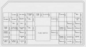
Dashboard (driver’s side)
Inside the fuse / relay panel covers, there is a fuse / relay label describing the name and capacity of the fuse / relay.

| Fuse name | Fuse [A] | Protected circuit |
| MULTI MEDIA 1 | 25 | DC-DC low voltage converter (Audio |
| AIR BAG | 15 | SRS (Supplemental Restraint System) control module |
| INTERIOR LAMP | 10 | Overhead console lamp, center room lamp, room lamp, vanity Left side / right side lamp switch, trunk lamp Left right side / right side lamp, glove box lamp, driver / passenger lamp, driver / passenger door lamp, driver / passenger foot lamp |
| STOP LIGHT | 10 | IBU, stop light switch |
| GROUP | 10 | Instrument cluster, Head-Up display |
| E-SHIFTER 2 | 10 | Automatic transmission gearshift lever (IG1) |
| IBU 4 | 10 | IBU (IG1) |
| MULTI MEDIA 3 | 10 | Instrument cluster, Head-Up display, air conditioning switch |
| MULTI MEDIA 2 | 15 | Audio |
| MEMORY 1 | 10 | Air conditioner control unit, air conditioner switch, safety indicator, Head-Up display |
| IBU 3 | 10 | IBU (B +) |
| E-SHIFTER 1 | 10 | Electronic automatic transmission gearshift lever (B +) |
| A / BAG IND. | 10 | Instrument cluster, passenger airbag IND |
| IBU 1 | 15 | IBU (B +) |
| DAU | 10 | Driver’s door module, driver’s / passenger’s outside mirror power supply |
| MODULE 2 | 10 | IBU (IG2) |
| MODULE 3 | 10 | Automatic transmission shift lever switch, driver’s door module, stop light switch |
| DOOR LOCK | 20 | Door lock relay, door unlock relay, two-speed unlock relay |
| S / HEATERDRV / PASS | 25 | Front ventilation control module, front seat heater control module |
| TAILGATE | 10 | Tailgate cover relay, fuel cover relay, bumper switch |
| IBU 2 | 10 | Rain sensor |
| POWER SOCKET 1 | 20 | Front power socket # 2 |
| MODULE 8 | 10 | Cooling fan controller (BLDC motor), Monitor all around, Front ventilation seat control module,Front/rearseatheater control module |
| MODULE 7 | 10 | IBU, ECS unit, AWD (all-wheel drive) ECM (electronic control module), intelligent cruise control, automatic transmission shift lever indicator, console switch (front / top), blind spot collision warning unit Left side of the handle / right side of the handle , Steering angle sensor, tilt and telescoping module, multifunction camera module, crash switch |
| POWER HANDLE | 15 | Steering wheel tilt and telescopic module |
| MODULE 9 | 10 | Driver’s lumbar air control unit |
| MODULE 1 | 10 | Data link connector, console switch (top), mood lamp control unit |
| MODULE 5 | 10 | Air conditioning control module, Air conditioning switch, Audio, Front side Left handle / Right side, DC-DC low voltage converter (Audio / AMP (amplifier)), Electrochromic mirror, AMP (amplifier), Integrated memory system control module , Front ventilation seat control module, front / rear Seatheater control module |
| SUNROOF | 20 | Sunroof control unit (glass) |
| P / WINDOW RH | 25 | Passenger window module, right side rear window module |
| POWER SOCKET 2 | 20 | Rear power socket |
| WASHING MACHINE | 15 | Multifunction switch |
| MDPS | 10 | MDPS (power-assisted power steering) unit (R-MDPS (power-assisted power steering)) |
| P / SEAT (DRV) | 30 | Integrated driver memory system control module, driver seat module |
| P / SEAT (PASS) | 30 | Passenger seat module |
| P / WINDOW LH | 25 | Driver’s window module, rear window module left handle side |
| MODULE 6 | 10 | IBU, DC-DC low-voltage converter (Audio / AMP (amplifier)), automatic transmission electronic shift lever (SBW (Shift Wire)), connection block in the engine compartment (RLY. 4 – power socket relay) |
| A / CON | 10 | Air conditioning control module, air conditioning switch, engine compartment connection block (blower relay) |
| MODULE 4 | 10 | Headlamp Left handle / right side, AFS control unit, automatic headlamp leveling module |
Engine compartment fuse panel

artment
| Fuse name | Fuse [A]. | Protected circuit |
| ALT | 175 | Alternator, multifunction fuse – COOLING VENTILATOR 1 / B + 5 / B + 4 / B + 3 / OPCU / ESC1 / ESC2 / DRYER / POWER GATE |
| 200 | ||
| COOLING FAN 2 | 125 | [BLDC (brushless DC) motor] cooling fan controller |
| START | 30 | Start the relay |
| COOLING FAN 1 | 80 | [BLDC (brushless DC) motor] Cooling fan controller |
| B + 5 | 50 | Control board connection block (fuse – STOP LAMP / leakage current fuse Automatic device fuse / INTERNAL LAMP) |
| B + 4 | 50 | Instrument panel connection block (fuse – DOOR LOCK / LOCKER / SUNROOF / P / SEAT (DRV) / P / SEAT (PASS)) |
| B + 3 | 50 | Instrument panel connection block (fuse – S / HEATER DRV / PASS / TAIL GATE / MODULE9 / P / WINDOW RH / P / WINDOW LH) |
| OPCU | 50 | Electric oil pump inverter |
| ESC 1 | 40 | ESC (Electronic Stability Control) control module |
| ESC 2 | 40 | ESC (Electronic Stability Control) control module, universal control connector |
| DMUCHER | 40 | Blower relay |
| TAIL POWER GATE | 30 | Power Tail Gate module |
| MDPS | 100 | MDPS (motor-driven power steering) unit |
| B + 6 | 60 | Motor control relay, fuse – HORN / WIPER1 / H / LAMP H / B / ALARM HORN) |
| B + 1 | 60 | Switchboard connection block (fuse – IBU1 / IBU2) |
| B + 2 | 50 | Switchboard connection block (fuse – E-SHIFTER1 / MODULE1) |
| E-CVVT 1 | 40 | [THETA II 2.0L T-GDI engine] E-CVVT relay |
| VACUUM PUMP | 20 | Vacuum pump relay |
| AWD | 20 | AWD (all-wheel drive) ECM (electronic control module) |
| IG 2 | 20 | IG2 relay |
| POWER SOCKET 2 | 10 | Front / rear USB charger, front power socket # 2 |
| POWER SOCKET 1 | 20 | Front power socket #1 |
| A / C | 10 | Air conditioner control module |
| E-CVVT 3 | 20 | [THETA II 2.0L T-GDI engine] ECM (engine control module). |
| E-CVVT 2 | 20 | [THETA II 2.0L T-GDI engine] ECM (engine control module). |
| ESC 3 | 10 | ESC (Electronic Stability Control) control module, universal control connector |
| ECU 3 | 10 | ECM (engine control module) |
| ECU 2 | 15 | ECM (engine control module) |
| HORN | 20 | Horn relay |
| WIPER 1 | 30 | Wiper power relay |
| TCU 2 | 15 | TCM (transmission control module) |
| SENSOR 4 | 10 | Brake vacuum switch, vacuum pump relay, electric oil pump inverter |
| TCU 1 | 20 | TCM (transmission control module) |
| WIPER 2 | 10 | IBU (integrated body control unit), ECM (electronic control module) |
| SENSOR 1 | 15 | Rear auxiliary connector block (fuel pump relay) |
| SENSOR 5 | 20 | [THETA II 2.0L T-GDI engine] Ignition coil # 1 / # 2 / # 3 / # 4[Lambda II 3.3L T-GDI engine] Ignition coil # 1 / # 2 / # 3 / # 4 / # 5 / # 6 |
| H / LAMP HI | 10 | Headlight relay (high) |
| ECU 1 | 20 | ECM (engine control module) |
| SENSOR 3 | 15 | [THETA II 2.0L T-GDI engine] Oxygen sensor (up)[Lambda II 3.3L T-GDI engine] Oxygen sensor #2 / # 4 |
| SENSOR 2 | 10 | [THETA II 2.0L T-GDI engine] Electronic thermostat, oil control valve, drain control solenoid valve, RCV control solenoid valve (recirculation valve control), canister shut-off valve[Lambda II 3.3L T-GDI] Electronic thermostat, oil pressure solenoid valve, oil control valve #1 / # 2 / # 3 / # 4 (inlet / outlet), RCV (recirculation valve control) Control solenoid valve, purge control Solenoid valve, canister closure valve |
| B / ALARM INDICATOR | 10 | Intruder alarm signal relay |
Relay
| Relay name | Type |
| Vacuum pump relay | ISO HC MICRO |
| B / Alarm siren relay | ISO MICRO |
| Power socket relay | ISO HC MICRO |
| Blower relay | ISO HC MICRO |
| Start relay | ISO HC MICRO |
| E-CVVT relay (G4KL) | ISO MICRO |
Rear fuse box panel

artment
| Fuse name | Ampere current [A]. | Protected circuit |
| ECS | 15 | ECS (Electronic Control Suspension) unit |
| S /REARHEATER | 20 | Rear seat heater control module |
| HEATEDMIRROR | 10 | A/C switch, driver / passenger outside mirror power supply |
| FUEL PUMP | 20 | Fuel pump relay |
| SPARE PART 1 | 10 | – |
| SPARE2 | 15 | – |
| SPARE3 | 15 | – |
| REAR HEATED | 30 | Rear heated relay |
| AMP 2 | 25 | AMP (amplifier) (MOBIS / PREMIUM) |
| SPARE4 | 15 | – |
| AMP 1 | 30 | DC-DC low voltage converter (AMP (amplifier)) |
| IG 1 | 40 | IG1 / ACC relay |
Battery terminal cover

| Fuse name | Ampere current [A] | Protected circuit |
| B + 1 | 80 | Rear auxiliary connector block (fuse – FUEL PUMP / REAR HEAT / AMP1) |
| B + 2 | 80 | Rear connection block (fuse – ECS / S / HEATER REAR / IG1). |
| FUSE | 40 | Connection block in the engine room (output relay), fuse -START / ECU2 / TCU1) |
| AMS | 10 | Battery sensor |