
Ford Escape II (2008-2012) has a passenger-compartment fuse panel on the right side of the center console and a Power Distribution Box in the engine compartment. Ford changed several assignments during production and also revised the under-hood diagram, so the year-dependent rows are kept intact.
The closely related Mercury Mariner 2008-2011 shares much of the CD2 electrical architecture, but individual equipment and model-year assignments can differ.
Where are the fuse boxes?
Passenger compartment: on the right side of the center console, low on the passenger side of the dashboard. Remove the access trim, then release the fuse-panel cover.
Engine compartment: the Power Distribution Box is beside the air-filter housing and contains the high-current fuses and relays for the fuel pump, ABS, starter, cooling fans, wipers and trailer circuits.
Passenger-compartment fuse panel
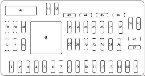
| Position | Rating [A] | Protected component / function |
|---|---|---|
| 1 | 30 | Spare / not used |
| 2 | 15 | Stop-lamp switch |
| 3 | 15 | SYNC module |
| 4 | 30 | Moonroof |
| 5 | 10 | Keypad illumination, brake-shift interlock, passenger-compartment fuse panel / SPDJB |
| 6 | 20 | Turn signals, stop lamps |
| 7 | 10 | Left low beam |
| 8 | 10 | Right low beam |
| 9 | 15 | Interior lamps |
| 10 | 15 | Illumination |
| 11 | 10 | Four-wheel drive |
| 12 | 7.5 | Power-mirror switch |
| 13 | 7.5 | 2008: EVAP canister vent valve |
| 14 | 10 | FCIM radio controls, front display module, GPS module |
| 16 | 15 | Spare / not used |
| 17 | 20 | Power door-lock motors, liftgate and liftgate-glass release |
| 18 | 20 | Heated seats |
| 19 | 25 | Rear wiper |
| 20 | 15 | Diagnostic / data link connector |
| 21 | 15 | Fog lamps |
| 22 | 15 | Parking lamps |
| 23 | 15 | High beams |
| 24 | 20 | Horn relay |
| 25 | 10 | Demand lighting |
| 26 | 10 | Instrument cluster |
| 27 | 20 | Ignition switch |
| 28 | 5 | Radio |
| 29 | 5 | Instrument cluster |
| 30 | 5 | Overdrive cancel |
| 31 | 10 | Restraints Control Module |
| 32 | 10 | Rear video camera module |
| 33 | 10 | Speed-control switch |
| 34 | 5 | Speed-control deactivation switch, ABS |
| 35 | 10 | Four-wheel drive, EPAS, parking-aid module |
| 36 | 5 | PATS transceiver |
| 37 | 10 | Climate control |
| 38 | 20 | Subwoofer / amplifier – Audiophile radio |
| 39 | 20 | Radio |
| 40 | 20 | Front power outlet |
| 41 | 15 | Driver/passenger door switches, auto-dimming mirror, compass, ambient lighting, moonroof, mirror-mounted camera display |
| 42 | 10 | Spare / not used |
| 43 | 10 | Rear-wiper logic, heated-seat relay coils, instrument cluster |
| 44 | 10 | Spare / not used |
| 45 | 5 | Front-wiper logic, blower-motor relay |
| 46 | 7.5 | Occupant Classification System, Passenger Airbag Deactivation Indicator |
| Circuit breaker | ||
| 47 | 30 | Power windows, moonroof |
| Relay | ||
| 48 | Relay | Delayed accessory power |
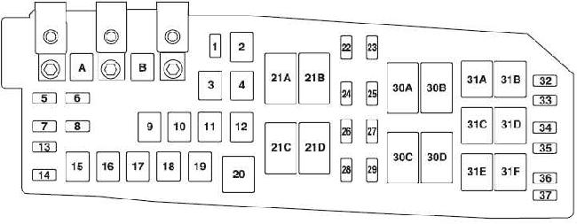
Engine-compartment power distribution box
Earlier 2008-2009 layout
Later 2010-2012 layout
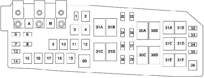
| Position | Rating [A] | Protected component / function |
|---|---|---|
| A | 80 | Electronic Power Assist Steering module |
| B | 125 | Passenger-compartment fuse panel |
| 1 | 15 | Heated mirror |
| 2 | 30 | Heated rear window |
| 3 | 20 | Rear center-console power outlet |
| 4 | 20 | 2008: fuel pump |
| 5 | 10 | PCM keep-alive memory, PCM relay, EVAP canister vent – 2009 onward |
| 6 | 15 | Alternator |
| 7 | 15 | Liftgate latch |
| 8 | 20 | Trailer parking lamps |
| 9 | 50 | Anti-lock Brake System |
| 10 | 30 | Front wipers |
| 11 | 30 | Starter |
| 12 | 40 | Blower motor |
| 13 | 10 | A/C clutch |
| 14 | 15 | Trailer marker lamps |
| 15 | – | Not used |
| 16 | 40 | Cooling fan 1 |
| 17 | 40 | Cooling fan 2 |
| 18 | 20 | ABS solenoid |
| 19 | 30 | Power seats |
| 22 | 20 | 2009 onward: fuel pump |
| 23 | 15 | 2009 onward: fuel injectors |
| 24 | 10 | 2008: PCM / transmission control |
| 25 | 5 | 2009 onward: ABS |
| 26 | 15 | 2009 onward: ignition coils |
| 10 | 2008: PCM MIL circuit | |
| 27 | 10 | PCM – general powertrain malfunction-indicator circuit |
| 28 | 20 | 2009 onward: PCM emission-related / MIL circuits |
| 15 | 2008: PCM | |
| 29 | 15 | 2009 onward: PCM. 2008: ignition coils |
| 32 | – | Not used |
| 35 | 10 | Reversing lamps, heated rear-window relay |
| 36 | – | Not used |
| 37 | – | Through 2009: not used |
| Relay | ||
| 20 | Relay | A/C clutch |
| 21A | Relay | Heated rear window |
| 21B | Relay | 2009 onward: fuel pump |
| 21C | Relay | Blower |
| 21D | Relay | PCM |
| 30A | Relay | Cooling fan 1 |
| 30B | Relay | Starter |
| 30C | Relay | Main cooling-fan relay |
| 30D | Relay | Cooling fan 2 |
| 31A | Relay | Reversing lamps |
| 31B | Relay | Not used |
| 31C | Relay | Left trailer turn signal |
| 31D | Relay | Right trailer turn signal |
| 31E | Relay | Trailer parking lamps |
| 31F | Relay | Liftgate latch |
| Diode | ||
| 33 | Diode | PCM diode |
| 34 | Diode | Starter diode |
Important model-year differences
Fuel pump: the 2008 layout uses position 4 – 20 A. From 2009, the fuel-pump circuit is listed at position 22 – 20 A with relay 21B.
SYNC: cabin position 3 – 15 A supplies the SYNC module on equipped vehicles.
Under-hood layout: the diagram changed for later 2010-2012 vehicles, while the table above retains the year-dependent assignments separately.
FAQ – Ford Escape 2008-2012 fuses
Where is the OBD-II / diagnostic connector fuse?
Cabin position 20 – 15 A.
Why does the fuel-pump fuse move between 2008 and 2010?
Ford revised the power distribution during production. The 2008 circuit is position 4 – 20 A, while later vehicles use position 22 – 20 A.
The front 12 V outlet is dead but the rear outlet works – what should I check?
The front outlet uses cabin position 40 – 20 A. The rear center-console outlet uses under-hood position 3 – 20 A.
Which fuse supplies the liftgate release?
Cabin position 17 – 20 A covers the power-lock motors and the liftgate/liftgate-glass release. The under-hood box also contains the liftgate-latch circuit and relay on later layouts.