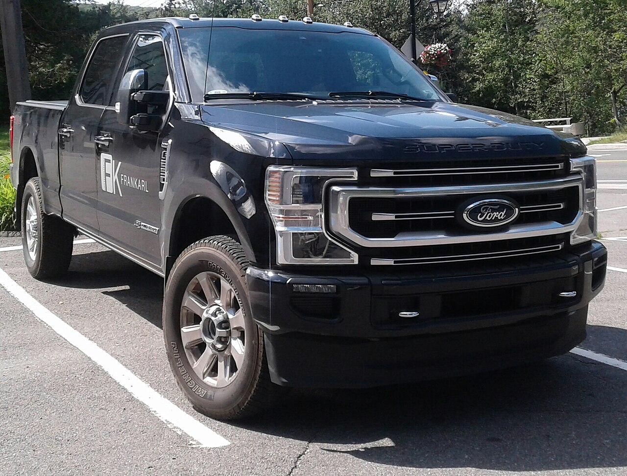
The 2020 Ford F-250 Super Duty uses two main fuse panels and, on trucks equipped with the factory auxiliary switches, an additional Upfitter relay and fuse box. Ford also assigns some fuse positions differently depending on whether the truck has the 6.2-liter or 7.3-liter gasoline engine or the 6.7-liter Power Stroke diesel.
Do not copy fuse numbers from the 2021 Ford F-150. Both are full-size Ford pickups, but the F-250 Super Duty uses a different electrical architecture, different trailer and body-equipment circuits, and several circuits specific to the 6.7-liter diesel.
Where are the fuse boxes in a 2020 Ford F-250?
Engine-compartment fuse box: located under the hood, high along the side of the engine bay near the battery assembly and cowl area. The exact surrounding components differ between the 6.2, 7.3 and 6.7 engines, but the fuse box is the large black module containing high-current positions 1-70. Disconnect the 12 V battery before servicing high-current fuses.
Passenger-compartment fuse panel: located on the right-hand side of the front passenger footwell, behind the side trim panel. Pull the trim panel toward you and move it aside. Ford notes that removing an additional trim piece can make access easier.
Upfitter relay box: on trucks with the six factory AUX switches, this box is in the engine compartment. The blunt-cut wires for connecting auxiliary equipment are routed under the instrument panel on the right-hand side of the passenger footwell.
Engine-compartment fuse box
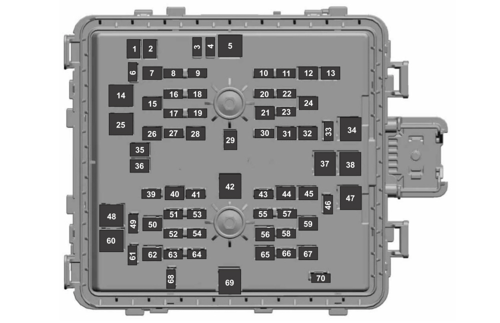
| Fuse | Rating [A] | Protected component / function |
|---|---|---|
| 1 | 20 | Power point 4 |
| 2 | 20 | Power point 3 |
| 3 | 10 | Spot lamp module |
| 4 | 10 | 4×4 vacuum solenoid |
| 5 | 40 | Active steering |
| 6 | 10 | Snow plow |
| 7 | 30 | Trailer battery charge |
| 8 | 10 | Anti-lock brake system module |
| 9 | 10 | Electronic power-assist steering module |
| 10 | 30 | Trailer parking lamps |
| 11 | 20 | Horn |
| 12 | 30 | Torque-overlay steering system |
| 13 | 30 | Power sliding rear window |
| 14 | 40 | Body control module battery feed 1 |
| 15 | 30 | Passenger power seat |
| 16 | 10 | Powertrain control module and transmission control module |
| 17 | 10 | Blind Spot Information System |
| 18 | 10 | 4×4 module |
| 19 | 5 | Adaptive cruise control |
| 20 | 15 | Heated mirrors |
| 21 | 40 | Heated rear window |
| 22 | 10 | OBD-II / Smart Data Link |
| 23 | 15 | Transmission control module |
| 24 | 30 | Driver power seat |
| 25 | 25 | Voltage Quality Module |
| 26 | 30 | Trailer battery charge |
| 27 | 20 | Rear heated seats |
| 28 | 25 | Glow plug module – diesel; not used – gasoline |
| 29 | 40 | Electronic power-assist steering motor |
| 30 | 10 | Heated wiper park area |
| 31 | 20 | Power point 5 |
| 32 | 25 | 4×4 module |
| 33 | 10 | Alternator sense line 2 |
| 34 | 50 | Cooling fan – gasoline; supplemental air heater – diesel |
| 35 | 20 | Power point 2 |
| 36 | 20 | Power point 1 |
| 37 | 60 | Anti-lock brake system pump |
| 38 | 60 | Inverter |
| 39 | 25 | 4×4 module |
| 40 | 30 | Starter solenoid |
| 41 | 10 | Tailgate release |
| 42 | 40 | Blower motor |
| 43 | 10 | Trailer backup lamps |
| 44 | 40 | Trailer lighting module |
| 45 | 30 | Anti-lock brake system valves |
| 46 | 30 | CNG module – if equipped |
| 47 | 50 | Supplemental heater – diesel; not used – gasoline |
| 48 | 50 | Supplemental heater – diesel; not used – gasoline |
| 49 | – | Not used |
| 50 | 30 | Heated and ventilated seats |
| 51 | 20 | Powertrain control module |
| 52 | 15 | CNG – gasoline / fuel rail pressure control – diesel |
| 53 | 20 | EGR and oxygen sensors – gasoline; EGR cooler bypass, reductant pump control and sensors – diesel |
| 54 | 20 | A/C clutch relay, fan clutch |
| 55 | 5 | Rain sensor |
| 56 | 30 | Windshield wipers |
| 57 | 10 | Upfitter interface module |
| 58 | 10 | Alternator sense line |
| 59 | 30 | Power running boards |
| 60 | 40 | Body control module battery feed 2 |
| 61 | 10 | Telescoping mirror motors |
| 62 | 40 | Trailer brake controller / auxiliary e-brake access |
| 63 | 15 | Multi-contour seats |
| 64 | 20 | Ignition coils – gasoline; glow plug module, NOx and DEF-quality sensor – diesel |
| 65 | 30 | Fuel pump |
| 66 | 10 | A/C clutch solenoid |
| 67 | 40 | Auxiliary lighting module |
| 68 | 10 | Powertrain control module |
| 69 | 60 | Body control module power |
| 70 | 30 | Trailer stop/turn lamps |
Engine-specific assignments matter on the Super Duty. Fuse 28 is used by the diesel glow-plug system, fuses 47 and 48 supply supplemental heating on the 6.7 Power Stroke, and fuse 64 supplies the ignition coils on gasoline engines but covers the glow-plug module, NOx system and DEF-quality sensor on the diesel. This is why an F-150 gasoline fuse chart should not be used as a reference when diagnosing a Power Stroke.
Passenger-compartment fuse panel
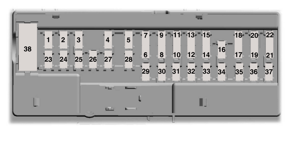
| Fuse | Rating [A] | Protected component / function |
|---|---|---|
| 1 | – | Not used |
| 2 | 10 | Driver door switch panel, power sliding rear-window switch |
| 3 | 7.5 | Memory seat, lumbar support, wireless charger |
| 4 | 20 | Not used (spare) |
| 5 | – | Not used |
| 6 | 10 | Telescoping mirror switch, front windows |
| 7 | 10 | Brake light switch |
| 8 | 5 | Modem |
| 9 | 5 | Combined sensor module |
| 10 | – | Not used |
| 11 | – | Not used |
| 12 | 7.5 | OBD-II / Smart Data Link, climate control |
| 13 | 7.5 | Steering column control module, instrument cluster |
| 14 | 15 | Not used (spare) |
| 15 | 15 | SYNC, display |
| 16 | – | Not used |
| 17 | 7.5 | Active steering, park assist |
| 18 | 7.5 | Drive modes, SelectShift |
| 19 | 5 | Head-up display |
| 20 | 5 | Ignition switch, key lock |
| 21 | 5 | Head-up display, cabin temperature and humidity sensor |
| 22 | 5 | Upfitter switches |
| 23 | 30 | Driver door module |
| 24 | 30 | Moonroof |
| 25 | – | Not used |
| 26 | 30 | Passenger door module |
| 27 | – | Not used |
| 28 | 30 | Audio amplifier |
| 29 | 15 | Adjustable pedals |
| 30 | 5 | Brake-light output to trailer brake controller and upfitter circuits |
| 31 | 10 | Remote keyless entry |
| 32 | 20 | Radio |
| 33 | – | Not used |
| 34 | 30 | Run/start relay |
| 35 | – | Not used |
| 36 | 15 | Camera, Lane Keeping, electrochromic mirror, rear heated seats |
| 37 | 20 | Heated steering wheel |
| 38 | 30 | Power-window circuit breaker |
Factory Upfitter / AUX switches
The F-250 can be equipped with six factory AUX switches for auxiliary lighting, body equipment, a winch or other work accessories. Ford provides separate relays and fuses for these circuits so accessories do not need to be powered from unrelated body-control circuits.
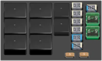
| Position | Rating [A] | Protected component / function |
|---|---|---|
| R1 | relay | Upfitter 1 |
| R2 | relay | Upfitter 2 |
| R3 | relay | Upfitter 3 |
| R4 | relay | Upfitter 4 |
| R5 | relay | Upfitter 5 |
| R6 | relay | Upfitter 6 |
| R7 | relay | PTO – power take-off |
| R8 | relay | Reset |
| F1 | 40 | Upfitter 5 |
| F2 | 40 | Upfitter 6 |
| F3 | 20 / 25 | Upfitter run/start relay |
| F4A | 5 | Upfitter switches |
| F4C | 5 | Upfitter switches |
| F5 | 20 / 25 | PTO relay |
| F6 | 20 | Customer access |
| F7 | 25 | Upfitter 4 |
| F8 | 25 | Upfitter 3 |
| F9 | 25 | Upfitter 2 |
| F10 | 25 | Upfitter 1 |
FAQ – 2020 Ford F-250 Super Duty fuses
Why is fuse 28 rated at 25 A on the diesel but unused on gasoline trucks?
On the 6.7 Power Stroke, fuse 28 protects the glow-plug system. The 6.2 and 7.3 gasoline engines do not use glow plugs, so Ford lists the position as unused.
What should I check if the factory AUX switches do not power auxiliary lights?
Start with passenger-panel fuse 22 – 5 A for the switches, under-hood fuse 57 – 10 A for the upfitter interface module, and the appropriate F1-F10 fuse and R1-R6 relay in the Upfitter box.
The trailer lights work but the electric trailer brakes do not. Which circuit is separate?
The trailer brake controller has a dedicated 40 A fuse at position 62 under the hood. Passenger-panel fuse 30 – 5 A carries the brake-light signal to the trailer brake controller and upfitter circuits.
Why can one 12 V power point fail while the others still work?
The Super Duty uses several separately protected power points. Under-hood fuses 1, 2, 31, 35 and 36 protect different outlets, so one blown fuse does not necessarily disable the others.
Do fuses 34, 47, 48, 52 and 64 have the same function on the 6.7 diesel and 7.3 gasoline engine?
No. Ford assigns several of these positions differently by engine. Check whether the truck has the 6.2/7.3 gasoline engine or the 6.7 Power Stroke before replacing or diagnosing the fuse.