
The second-generation Ford Scorpio, commonly known as Scorpio ’95 (late 1994-1998), uses two principal under-bonnet fuse boxes: the Central Junction Box (CJB) and the Battery Junction Box (BJB). Unlike some earlier Scorpios, the principal fuse distribution is not beneath the dashboard. This guide preserves all standard numbered positions 1-47, four high-current fusible links I-IV and the main and distributed relay positions, including unused locations and left/right-hand-drive differences. The reference arrangement follows Ford Scorpio ’95 service documentation revised in November 1997.
Where are the Ford Scorpio II fuse boxes?
Central Junction Box: Open the bonnet and locate the covered electrical carrier at the rear of the engine bay on the driver’s side. Release the lid catches and lift away the cover. Its fuse positions are 1-29, and relay sockets use the identifiers R1-R14. On cars built for right-hand-drive markets, do not assume the left-hand side of a reference drawing is the driver’s side.
Battery Junction Box: This second carrier is mounted towards the back of the engine bay on the passenger side. Release its cover catch, lift the lid sections in sequence and check the original fuse legend. It contains fuses 30-47, high-current fusible links I-IV, relays R16-R25 and some bridge positions. High-current fusible links should be serviced using Ford’s electrical procedure, not pulled out like a small blade fuse.
Other relays: Additional units may be mounted behind the glovebox, around the steering column, inside the driver’s door, beside the sunroof or in the engine compartment. Their identifiers R26-R38 do not mean they are all inside either of the main fuse boxes.
Central Junction Box – fuses 1-29 and relays R1-R14
This box covers lighting, wipers, interior electronics, electric windows and the heater blower. The table also preserves relays, an unused relay socket R8, and market-specific daylight running light and dim/dip equipment.
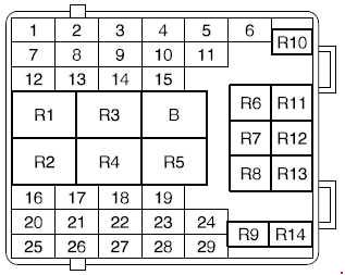
| Pozycja | Amperaż [A] | Chroniony obwód / funkcja |
|---|---|---|
| 1 | 15 | Front fog lamps and heated exterior mirrors |
| 2 | 5 | Left parking lamp on left-hand-drive vehicles and licence plate lighting |
| 3 | 10 | Exterior lighting switch |
| 4 | 10 | Right-hand dipped beam and headlamp height adjustment |
| 5 | 10 | Left-hand dipped-beam headlamp |
| 6 | 30 | Power seat adjustment |
| 7 | 25 | Wiper motors and washer pumps |
| 8 | 5 | Radio supply |
| 9 | 15 | Horn |
| 10 | 10 | Left-hand main-beam headlamp |
| 11 | 10 | Right-hand main-beam headlamp |
| 12 | 5 | Right parking lamps on right-hand-drive versions |
| 13 | 20 | Ignition switch supply |
| 14 | 15 | Rear lights, indicators and brake lamps |
| 15 | 7.5 | Rear fog lamps |
| 16 | 7.5 | Vehicle electronics, first feed |
| 17 | 7.5 | Vehicle electronics, second feed |
| 18 | 10 | Dimmed / dipped lighting circuit on right-hand-drive versions |
| 19 | 20 | Headlamp washer system |
| 20 | 20 | Rear-window heating |
| 21 | 10 | Heated exterior mirrors |
| 22 | 20 | Central door locking modules |
| 23 | 5 | Instrument cluster backlighting |
| 24 | 15 | Interior lamps and audio system |
| 25 | 30 | Electric window system |
| 26 | 30 | Front electric window motors |
| 27 | 10 | SRS airbags and ABS electronics |
| 28 | 30 | Electric sunroof and rear power windows |
| 29 | 25 | Heater blower motor |
| R1 | – | R1 – Rear-window wiper relay |
| R2 | – | R2 – Windscreen intermittent wiper relay |
| R3 | – | R3 – Dipped-beam relay |
| R4 | – | R4 – Rear-window heater relay, first |
| R5 | – | R5 – Rear-window heater relay, second |
| R6 | – | R6 – Main-beam relay |
| R7 | – | R7 – Dimmed / dipped-beam relay for British-market vehicles |
| R8 | – | R8 – Unoccupied relay socket |
| R9 | – | R9 – Front fog lamp relay |
| R10 | – | R10 – Horn relay |
| R11 | – | R11 – Starter inhibitor relay for automatic transmission |
| R12 | – | R12 – Rear door locking relay |
| R13 | – | R13 – Electrical bridge / jumper |
| R14 | – | R14 – Daytime running lamps on Scandinavian-market models (Sweden, Norway, Denmark and Finland) |
Battery Junction Box – fuses 30-47, links I-IV and relays R16-R25
The battery box contains engine management, air-conditioning and cooling feeds, heated windscreen supply and ABS, together with the large main links. Both halves of the heated front windscreen are protected separately by 30 A fuses 38 and 41. On diesel vehicles, high-current link IV (50 A) is associated with the glow-plug circuit.
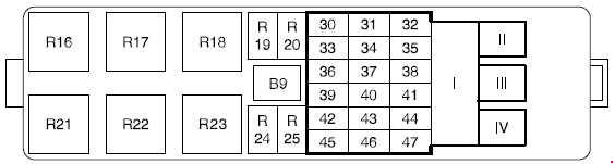
| Pozycja | Amperaż [A] | Chroniony obwód / funkcja |
|---|---|---|
| 30 | 20 | Self-levelling rear suspension |
| 31 | 10 | EEC V / PCM engine control module |
| 32 | – | Unused fuse position |
| 33 | 20 | Ignition timing supply |
| 34 | 15 | Engine management system |
| 35 | 30 | Air-conditioning compressor |
| 36 | 10 | Battery power-saving circuit |
| 37 | 20 | Engine management system |
| 38 | 30 | Right-hand heated windscreen zone |
| 39 | 30 | Cooling fan, first supply circuit |
| 40 | 20 | Heated oxygen sensor (HO2S) |
| 41 | 30 | Left-hand heated windscreen zone |
| 42 | 15 | Fuel pump |
| 43 | 20 | Cigarette lighter and electrically heated seats |
| 44 | 30 | Cooling fan, second supply circuit |
| 45 | 10 | Hazard warning flasher |
| 46 | 30 | ABS control module, first power feed |
| 47 | 30 | ABS control module, second power feed |
| I | 80 | Main power link for central junction box |
| II | 60 | Central junction box power feed II |
| III | 60 | Central junction box power feed III |
| IV | 50 | Diesel glow plug main fusible link |
| R16 | – | R16 – Battery power saver relay |
| R17 | – | R17 – Fuel injection pump relay |
| R18 | – | R18 – Heated windscreen relay |
| R19 | – | R19 – Engine management relay |
| R20 | – | R20 – Self-levelling suspension relay |
| R21 | – | R21 – Ignition switch relay |
| R22 | – | R22 – Electrical bridge / jumper |
| R23 | – | R23 – Electrical bridge / jumper |
| R24 | – | R24 – Air-conditioning relay |
| R25 | – | R25 – Unoccupied relay socket |
Auxiliary relays R26-R38 and where to find them
Unlike the preceding two groups, these units are distributed across the vehicle. Several are mounted behind the glovebox, but others are by the steering column, central console, doors, sunroof or engine bay. The descriptions identify the original mounting locations instead of incorrectly assigning these relays to the BJB or CJB. This list is not accompanied by a third box diagram because the relay positions are physically dispersed.
| Pozycja | Amperaż [A] | Chroniony obwód / funkcja |
|---|---|---|
| R26 | – | R26 – Heated seats relay, centre console |
| R27 | – | R27 – Electric sunroof relay, beside the roof mechanism |
| R28 | – | R28 – Heater blower relay, behind the passenger glovebox |
| R29 | – | R29 – Turn signal relay, near the steering column |
| R30 | – | R30 – Power-window overload cut-out, inside the driver’s door |
| R31 | – | R31 – Headlamp washer relay, behind the glovebox |
| R32 | – | R32 – Diesel glow plug relay, engine compartment |
| R33 | – | R33 – Intermittent rear wiper relay, near the steering column |
| R34 | – | R34 – Engine cooling fan relay, engine compartment |
| R35 | – | R35 – Front fog lamp relay for selected NL / Swedish market configurations, beneath dashboard |
| R36 | – | R36 – Unused auxiliary relay socket |
| R37 | – | R37 – Cruise control relay, behind the glovebox |
| R38 | – | R38 – Air compressor relay, behind the glovebox |
Important equipment and market variations
Some Scorpio configurations have self-levelling suspension, an automatic gearbox starter inhibitor, heated seats or a diesel glow-plug system. The daytime running light relay R14 applies to certain Scandinavian markets, while R7 and fuse 18 are associated with specific British lighting arrangements. A temporarily interrupted power window or seat adjustment circuit may also result from an overload cut-out rather than an ordinary blown fuse.
Heater blower, fuel pump and heated windscreen faults
Blower not working: Check CJB fuse 29 (25 A). If the feed is present, inspect auxiliary relay R28 behind the passenger glovebox and the blower motor and resistor/control components.
Headlamp faults: CJB fuses 4 and 5 (10 A each) protect the dipped beams, with relay R3 serving the circuit. Heated front windscreen: BJB fuse 38 protects the right-hand section and fuse 41 the left-hand section, both at 30 A; check relay R18 if neither heats.
Fuel delivery: BJB fuse 42 (15 A) and relay R17 are relevant to fuel system supply. 12 V lighter: BJB fuse 43 (20 A) also serves heated seats on equipped cars. With old wiring harnesses, fuse continuity alone does not establish that connectors and power distribution are in good condition.
Other Ford fuse-box generations
Ford’s later Mondeo Mk3 (2000-2007) uses different electrical panel locations and a different fuse numbering scheme. It is a useful comparison of how Ford power distribution developed after the Scorpio, not an interchangeable circuit reference.
Technical reference: Ford Scorpio ’95 “Basic Interior Electrical System”, November 1997 revision, and service wiring schedules for Central and Battery Junction Boxes. Confirm the exact build date, engine, market and equipment.