
The fifth-generation Ford Taurus was sold as model years 2008 and 2009. Although the vehicle was introduced during calendar year 2007, the renamed successor to the Five Hundred entered the market as the 2008 Taurus. For that reason the fuse tables below are separated by the correct model years.
The car uses two main fuse locations: the Smart Power Distribution Junction Box below the dashboard to the left of the steering wheel and the Power Distribution Box in the engine compartment.
The closely related Ford Taurus X 2007-2009 uses similar architecture but has extra crossover circuits for the rear wiper, power liftgate, auxiliary blower and third-row equipment, so its table should not be substituted for the sedan.
Where are the fuse boxes?
Passenger compartment: below the dashboard to the left of the steering wheel. It contains circuits for OBD-II, radio, lighting, PATS, AWD, the moonroof and delayed accessory power.
Engine compartment: the Power Distribution Box contains the high-current fuses and relays for the fuel pump, PCM, ABS, starter, blower and wipers.
Passenger-compartment fuse panel – 2008
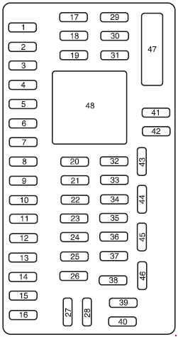
| Position | Rating [A] | Protected component / function |
|---|---|---|
| 1 | 30 | Driver one-touch window motor |
| 2 | 15 | Stop-lamp switch, center high-mounted stop lamp |
| 3 | 15 | SDARS satellite radio, Bluetooth, rear-seat entertainment / rear-seat controls |
| 4 | 30 | Spare |
| 5 | 10 | SPDJB logic supply |
| 6 | 20 | Turn signals |
| 7 | 10 | Left low beam |
| 8 | 10 | Right low beam |
| 9 | 15 | Interior and cargo-area lighting |
| 10 | 15 | Illumination and puddle lamps |
| 11 | 10 | AWD system |
| 12 | 7.5 | Seat/mirror memory switches and memory module |
| 13 | 5 | FEPS module |
| 14 | 10 | Analog clock |
| 15 | 10 | Climate-control system |
| 16 | 15 | Spare |
| 17 | 20 | Central-lock motors, liftgate release |
| 18 | 20 | Spare |
| 19 | 25 | Moonroof |
| 20 | 15 | OBD-II diagnostic connector |
| 21 | 15 | Front fog lamps |
| 22 | 15 | Parking lamps and license-plate lamps |
| 23 | 15 | High beams |
| 24 | 20 | Horn relay |
| 25 | 10 | Demand interior lighting |
| 26 | 10 | Instrument cluster |
| 27 | 20 | Adjustable pedals |
| 28 | 5 | Radio, radio start signal |
| 29 | 5 | Instrument cluster |
| 30 | 5 | Overdrive-cancel switch |
| 31 | 10 | Compass, electrochromic mirror |
| 32 | 10 | Restraints Control Module (RCM) |
| 33 | 10 | Spare |
| 34 | 5 | AWD module |
| 35 | 10 | Steering-angle sensor, FEPS, rear parking aid, heated-seat modules |
| 36 | 5 | PATS module |
| 37 | 10 | Climate-control system |
| 38 | 20 | Subwoofer – Audiophile system |
| 39 | 20 | Radio |
| 40 | 20 | Spare |
| 41 | 15 | Microphone mirror, moonroof, front door-lock switches, radio |
| 42 | 10 | Spare |
| 43 | 10 | Spare |
| 44 | 10 | Spare |
| 45 | 5 | Relay coils: PDB, auxiliary climate control, front/rear wipers and front blower |
| 46 | 7.5 | Occupant Classification System (OCS), passenger-airbag deactivation indicator (PADI) |
| 47 | 30 CB | Power windows – circuit breaker |
| 48 | Relay | Delayed accessory power |
Engine-compartment power distribution box – 2008
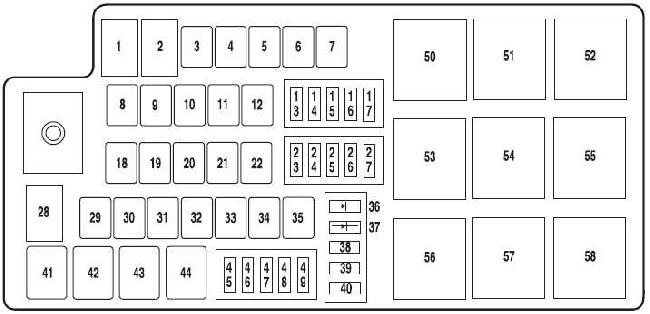
| Position | Rating [A] | Protected component / function |
|---|---|---|
| 1 | 80 | SPDJB supply |
| 2 | 80 | SPDJB supply |
| 3 | 30 | Front wipers |
| 4 | – | Not used |
| 5 | 20 | Spare |
| 6 | – | Not used |
| 7 | 50 | Engine cooling fan |
| 8 | – | Not used |
| 9 | 40 | ABS / AdvanceTrac pump |
| 10 | 30 | Starter |
| 11 | 50 | PCM relay |
| 12 | 20 | ABS / AdvanceTrac valves |
| 13 | 20 | Dashboard power outlet |
| 14 | 20 | Second-row power outlet |
| 15 | 20 | Spare |
| 16 | 20 | Console power outlet |
| 17 | 10 | Alternator |
| 18 | – | Not used |
| 19 | – | Not used |
| 20 | 40 | Heated rear window |
| 21 | 30 | Passenger power seat |
| 22 | 20 | Heated-seat module |
| 23 | 10 | PCM keep-alive memory, EVAP canister vent valve |
| 24 | 10 | A/C clutch relay |
| 25 | 25 | Spare |
| 26 | 20 | Reversing-lamp relay |
| 27 | 15 | Fuel-pump relay, fuel-pump driver module and fuel pump |
| 28 | – | Not used |
| 29 | 30 | Spare |
| 30 | – | Not used |
| 31 | 30 | Spare |
| 32 | 30 | Driver seat, memory module |
| 33 | 20 | Ignition switch – SJB supply |
| 34 | – | Not used |
| 35 | 40 | Front climate-control blower motor |
| 36 | 1 A diode | One-Touch Start system |
| 37 | 1 A diode | Fuel pump |
| 38 | 10 | IVD, yaw-rate sensor |
| 39 | 10 | Fuel-pump diode, PCM |
| 40 | – | Not used |
| 41 | Relay | A/C clutch |
| 42 | Relay | Fuel pump |
| 43 | Relay | Reversing lamps |
| 44 | – | Not used |
| 45 | 10 | Speed-control deactivation switch, MAF, VPWR2 module |
| 46 | 10 | A/C clutch relay, VPWR3 |
| 47 | 15 | PCM VPWR1 |
| 48 | 15 | PCM VPWR4 |
| 49 | 15 | Heated mirrors |
| 50 | Relay | PCM |
| 51 | – | Not used |
| 52 | – | Not used |
| 53 | Relay | Heated rear window |
| 54 | Relay | Blower motor |
| 55 | Relay | Starter |
| 56 | – | Not used |
| 57 | Relay | Front wiper |
| 58 | – | Not used |
Passenger-compartment fuse panel – 2009
The physical panel layout is unchanged, but several assignments differ. The key change is the Restraints Control Module moving from position 32 to position 33, together with a different use of position 31.
| Position | Rating [A] | Protected component / function |
|---|---|---|
| 1 | 30 | Driver one-touch window motor |
| 2 | 15 | Stop-lamp switch, center high-mounted stop lamp |
| 3 | 15 | SDARS satellite radio, Bluetooth, rear-seat entertainment / rear-seat controls |
| 4 | 30 | Spare |
| 5 | 10 | SPDJB logic supply |
| 6 | 20 | Turn signals |
| 7 | 10 | Left low beam |
| 8 | 10 | Right low beam |
| 9 | 15 | Interior and cargo-area lighting |
| 10 | 15 | Illumination and puddle lamps |
| 11 | 10 | AWD system |
| 12 | 7.5 | Seat/mirror memory switches and memory module |
| 13 | 5 | FEPS module |
| 14 | 10 | Analog clock |
| 15 | 10 | Climate-control system |
| 16 | 15 | Spare |
| 17 | 20 | Central-lock motors, liftgate release |
| 18 | 20 | Spare |
| 19 | 25 | Moonroof |
| 20 | 15 | OBD-II diagnostic connector |
| 21 | 15 | Front fog lamps |
| 22 | 15 | Parking lamps and license-plate lamps |
| 23 | 15 | High beams |
| 24 | 20 | Horn relay |
| 25 | 10 | Demand interior lighting |
| 26 | 10 | Instrument cluster |
| 27 | 20 | Adjustable pedals |
| 28 | 5 | Radio, radio start signal |
| 29 | 5 | Instrument cluster |
| 30 | 5 | Overdrive-cancel switch |
| 31 | 10 | Spare / not used |
| 32 | 10 | Spare / not used |
| 33 | 10 | Restraints Control Module (RCM) |
| 34 | 5 | AWD module |
| 35 | 10 | Steering-angle sensor, FEPS, rear parking aid, heated-seat modules |
| 36 | 5 | PATS module |
| 37 | 10 | Climate-control system |
| 38 | 20 | Subwoofer – Audiophile system |
| 39 | 20 | Radio |
| 40 | 20 | Spare |
| 41 | 15 | Moonroof, front door-lock switches, radio, electrochromic mirror with compass |
| 42 | 10 | Spare |
| 43 | 10 | Spare |
| 44 | 10 | Spare |
| 45 | 5 | Relay coils: PDB, auxiliary climate control, front/rear wipers and front blower |
| 46 | 7.5 | Occupant Classification System (OCS), passenger-airbag deactivation indicator (PADI) |
| 47 | 30 CB | Power windows – circuit breaker |
| 48 | Relay | Delayed accessory power |
Engine-compartment power distribution box – 2009
The physical box layout remains the same. In 2009, positions 5, 15, 25, 29 and 31 are listed as unused rather than the spare fuses shown in the 2008 table.
| Position | Rating [A] | Protected component / function |
|---|---|---|
| 1 | 80 | SPDJB supply |
| 2 | 80 | SPDJB supply |
| 3 | 30 | Front wipers |
| 4 | – | Not used |
| 5 | – | Not used |
| 6 | – | Not used |
| 7 | 50 | Engine cooling fan |
| 8 | – | Not used |
| 9 | 40 | ABS / AdvanceTrac pump |
| 10 | 30 | Starter |
| 11 | 50 | PCM relay |
| 12 | 20 | ABS / AdvanceTrac valves |
| 13 | 20 | Dashboard power outlet |
| 14 | 20 | Second-row power outlet |
| 15 | – | Not used |
| 16 | 20 | Console power outlet |
| 17 | 10 | Alternator |
| 18 | – | Not used |
| 19 | – | Not used |
| 20 | 40 | Heated rear window |
| 21 | 30 | Passenger power seat |
| 22 | 20 | Heated-seat module |
| 23 | 10 | PCM keep-alive memory, EVAP canister vent valve |
| 24 | 10 | A/C clutch relay |
| 25 | – | Not used |
| 26 | 20 | Reversing-lamp relay |
| 27 | 15 | Fuel-pump relay, fuel-pump driver module and fuel pump |
| 28 | – | Not used |
| 29 | – | Not used |
| 30 | – | Not used |
| 31 | – | Not used |
| 32 | 30 | Driver seat, memory module |
| 33 | 20 | Ignition switch – SJB supply |
| 34 | – | Not used |
| 35 | 40 | Front climate-control blower motor |
| 36 | 1 A diode | One-Touch Start system |
| 37 | 1 A diode | Fuel pump |
| 38 | 10 | IVD, yaw-rate sensor |
| 39 | 10 | Fuel-pump diode, PCM |
| 40 | – | Not used |
| 41 | Relay | A/C clutch |
| 42 | Relay | Fuel pump |
| 43 | Relay | Reversing lamps |
| 44 | – | Not used |
| 45 | 10 | Speed-control deactivation switch, MAF, VPWR2 module |
| 46 | 10 | A/C clutch relay, VPWR3 |
| 47 | 15 | PCM VPWR1 |
| 48 | 15 | PCM VPWR4 |
| 49 | 15 | Heated mirrors |
| 50 | Relay | PCM |
| 51 | – | Not used |
| 52 | – | Not used |
| 53 | Relay | Heated rear window |
| 54 | Relay | Blower motor |
| 55 | Relay | Starter |
| 56 | – | Not used |
| 57 | Relay | Front wiper |
| 58 | – | Not used |
FAQ – Ford Taurus 2008-2009 fuses
Where is the OBD-II fuse?
Cabin position 20 – 15 A in both model years.
The fuel pump does not run – what should I check?
Under-hood position 27 – 15 A supplies the fuel-pump circuit. Relay 42 controls the pump and position 37 is the pump diode.
Which fuses protect the 12 V power outlets?
Position 13 – 20 A is the dashboard outlet, position 14 – 20 A the second-row outlet and position 16 – 20 A the console outlet.
Why is the RCM fuse different in 2009?
In 2008 the Restraints Control Module uses cabin position 32 – 10 A. In 2009 Ford moved it to position 33 – 10 A and position 32 became spare.
Which fuses are related to AWD?
Cabin position 11 – 10 A and position 34 – 5 A are both associated with AWD functions.