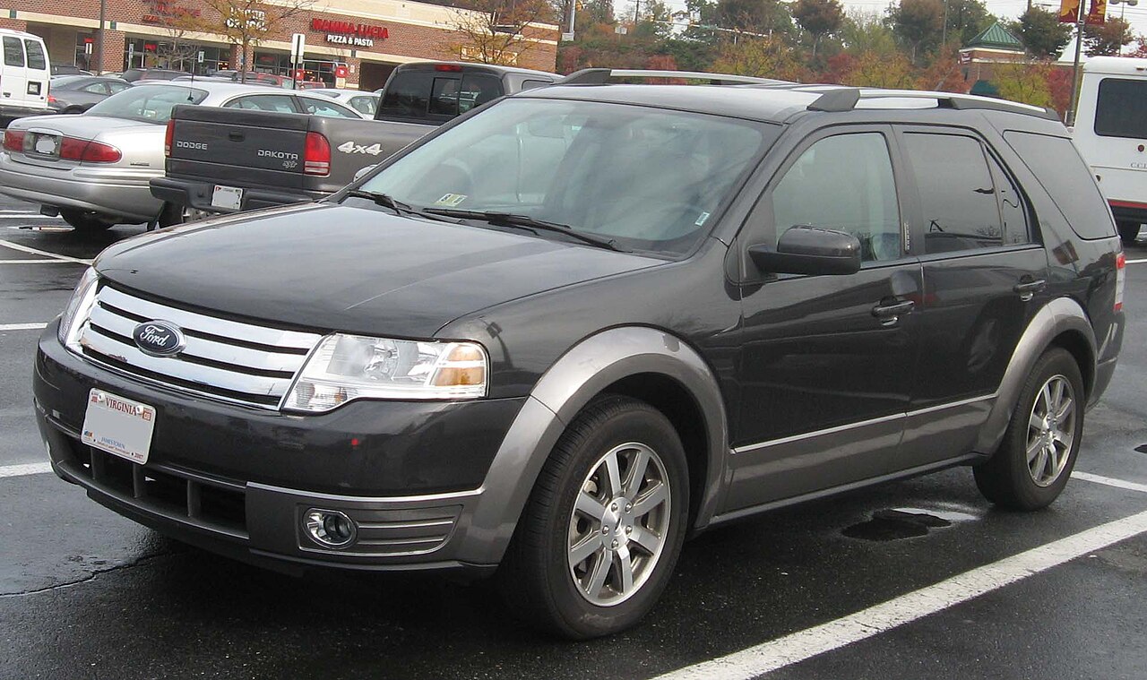
The Ford Taurus X (2007-2009) is the crossover successor to the Ford Freestyle. It uses two main fuse locations: the Smart Power Distribution Junction Box (SPDJB) below the dashboard on the driver’s side and the Power Distribution Box in the engine compartment.
Compared with the Ford Taurus 2008-2009 sedan, Taurus X adds crossover-specific circuits for the rear wiper, power liftgate, auxiliary blower and third-row power outlet. The tables below keep those assignments separate instead of mixing the two models.
Where are the fuse boxes?
Passenger compartment: below the dashboard to the left of the steering wheel, low on the driver’s side. This panel includes the OBD-II connector, radio, PATS, AWD, climate control, airbags and liftgate-control circuits.
Engine compartment: the Power Distribution Box contains the high-current fuses and relays for the fuel pump, ABS, starter, blowers, wipers, heated rear window and power liftgate.
Passenger-compartment fuse panel
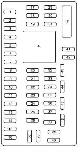
| Position | Rating [A] | Protected component / function |
|---|---|---|
| 1 | 30 | Driver one-touch window motor |
| 2 | 15 | Stop-lamp switch, center high-mounted stop lamp |
| 3 | 15 | SDARS satellite radio, Bluetooth, rear-seat entertainment / rear-seat controls |
| 4 | 30 | Spare |
| 5 | 10 | SPDJB logic supply |
| 6 | 20 | Turn signals |
| 7 | 10 | Left low beam |
| 8 | 10 | Right low beam |
| 9 | 15 | Interior and cargo-area lighting |
| 10 | 15 | Illumination and puddle lamps |
| 11 | 10 | AWD system |
| 12 | 7.5 | Seat/mirror memory switches and memory module |
| 13 | 5 | FEPS module |
| 14 | 10 | Power liftgate module |
| 15 | 10 | Climate-control system |
| 16 | 15 | Spare |
| 17 | 20 | Central-lock motors, liftgate release |
| 18 | 20 | Power-folding / power-operated second-row seat |
| 19 | 25 | Moonroof |
| 20 | 15 | OBD-II diagnostic connector |
| 21 | 15 | Front fog lamps |
| 22 | 15 | Parking lamps and license-plate lamps |
| 23 | 15 | High beams |
| 24 | 20 | Horn relay |
| 25 | 10 | Demand interior lighting |
| 26 | 10 | Instrument cluster |
| 27 | 20 | Adjustable pedals |
| 28 | 5 | Radio, radio start signal |
| 29 | 5 | Instrument cluster |
| 30 | 5 | Overdrive-cancel switch |
| 31 | 10 | 2008: compass and electrochromic mirror. 2009: spare / not used |
| 32 | 10 | 2008: Restraints Control Module (RCM). 2009: spare / not used |
| 33 | 10 | 2008: spare / not used. 2009: Restraints Control Module (RCM) |
| 34 | 5 | AWD module |
| 35 | 10 | Steering-angle sensor, FEPS, rear parking aid, heated-seat modules |
| 36 | 5 | PATS module |
| 37 | 10 | Climate-control system |
| 38 | 20 | Subwoofer – Audiophile system |
| 39 | 20 | Radio |
| 40 | 20 | Spare |
| 41 | 15 | Moonroof, front door-lock switches, radio; 2008 also microphone mirror, 2009 electrochromic mirror with compass |
| 42 | 10 | Spare |
| 43 | 10 | Spare |
| 44 | 10 | Spare |
| 45 | 5 | Relay coils: PDB, auxiliary climate control, front/rear wipers and front blower |
| 46 | 7.5 | Occupant Classification System (OCS), passenger-airbag deactivation indicator (PADI) |
| 47 | 30 CB | Power windows – circuit breaker |
| 48 | Relay | Delayed accessory power |
Engine-compartment power distribution box
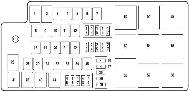
| Position | Rating [A] | Protected component / function |
|---|---|---|
| 1 | 80 | SPDJB supply |
| 2 | 80 | SPDJB supply |
| 3 | 30 | Front wipers |
| 4 | – | Not used |
| 5 | 20 | Rear heated-seat module |
| 6 | – | Not used |
| 7 | 50 | Engine cooling fan |
| 8 | – | Not used |
| 9 | 40 | ABS / AdvanceTrac pump |
| 10 | 30 | Starter |
| 11 | 50 | PCM relay |
| 12 | 20 | ABS / AdvanceTrac valves |
| 13 | 20 | Dashboard power outlet |
| 14 | 20 | Second-row power outlet |
| 15 | 20 | Third-row power outlet |
| 16 | 20 | Console power outlet |
| 17 | 10 | Alternator |
| 18 | – | Not used |
| 19 | – | Not used |
| 20 | 40 | Heated rear window |
| 21 | 30 | Passenger power seat |
| 22 | 20 | Heated-seat module |
| 23 | 10 | PCM keep-alive memory, EVAP canister vent valve |
| 24 | 10 | A/C clutch relay |
| 25 | 25 | Rear wiper |
| 26 | 20 | Reversing-lamp relay |
| 27 | 15 | Fuel-pump relay, fuel-pump driver module and fuel pump |
| 28 | – | Not used |
| 29 | 30 | Power liftgate |
| 30 | – | Not used |
| 31 | 30 | Auxiliary blower relay |
| 32 | 30 | Driver seat, memory module |
| 33 | 20 | Ignition switch – SJB supply |
| 34 | – | Not used |
| 35 | 40 | Front climate-control blower motor |
| 36 | 1 A diode | One-Touch Start system |
| 37 | 1 A diode | Fuel pump |
| 38 | 10 | IVD, yaw-rate sensor |
| 39 | 10 | Fuel-pump diode, PCM |
| 40 | 10 | Auxiliary coolant pump |
| 41 | Relay | A/C clutch |
| 42 | Relay | Fuel pump |
| 43 | Relay | Reversing lamps |
| 44 | Relay | Rear wiper |
| 45 | 10 | Speed-control deactivation switch, MAF, VPWR2 module |
| 46 | 10 | A/C clutch relay, VPWR3 |
| 47 | 15 | PCM VPWR1 |
| 48 | 15 | PCM VPWR4 |
| 49 | 15 | Heated mirrors |
| 50 | Relay | PCM |
| 51 | – | Not used |
| 52 | – | Not used |
| 53 | Relay | Heated rear window |
| 54 | Relay | Blower motor |
| 55 | Relay | Starter |
| 56 | – | Not used |
| 57 | Relay | Front wiper |
| 58 | – | Not used |
Differences between 2008 and 2009
The main change is in the cabin panel. In 2008 the Restraints Control Module uses position 32 – 10 A, while in 2009 it moves to position 33 – 10 A. Position 31 supplies the compass and electrochromic mirror in 2008 but is spare in 2009. The principal under-hood assignments remain essentially the same in the 2008 and 2009 manuals.
FAQ – Ford Taurus X 2007-2009 fuses
The rear wiper does not work – what should I check?
The main rear-wiper fuse is position 25 – 25 A under the hood. Also check relay 44 and the wiper-motor wiring.
Where is the power-liftgate fuse?
The liftgate motor is protected by position 29 – 30 A under the hood. Cabin position 14 – 10 A supplies the liftgate module, while position 17 also covers liftgate release.
Where is the OBD-II fuse?
Cabin position 20 – 15 A protects the diagnostic connector.
Which fuse protects the third-row 12 V outlet?
Under-hood position 15 – 20 A. The second-row outlet uses position 14 – 20 A and the console outlet position 16 – 20 A.
Which components are in the fuel-pump circuit?
Position 27 – 15 A supplies the fuel-pump circuit, relay 42 controls the pump and position 37 is the fuel-pump diode.