
The second-generation Kia Carens FJ (2002-2006) has a main fuse and relay box in the engine compartment, a separate panel low in the driver’s footwell and an additional relay assembly behind the dashboard. Diesel versions also use a dedicated high-current block for the alternator, glow plugs and auxiliary heaters. The original fuse legends and ratings are retained below, including the two separate ABS feeds and the cabin F5 position whose function is not specified in the available listing.
Where are the Kia Carens FJ fuse boxes?
Engine compartment: Switch the ignition off, open the bonnet and find the main black plastic fuse box next to the battery. Release the cover clip and lift the lid. Match the printed codes such as COOL FAN, F/PUMP and HEAD LOW to the diagram. The two ABS fuses have different ratings, 30 A and 25 A, and supply separate circuits.
Passenger compartment: Open the driver’s door and look below the dashboard near the driver’s footwell. Remove the small plastic access cover and identify the labelled fuses, including CIGAR, POWER SOCKET, RADIO and STOP LAMP. Right-hand-drive vehicles may have mirrored panel positioning.
Auxiliary relays: A further relay board sits beneath the dashboard. Its relay positions are numbered separately from the fuse codes. Some relays may be absent if the relevant feature, such as heated seats or daytime running lights, was not installed.
Diesel engines: The high-current block is located by the main engine compartment fuse assembly. Remove its protective cover to identify the alternator, glow-plug and electric supplementary-heater links. Use the diesel-specific diagram and do not assume this block is fitted to a petrol Carens.
Main engine compartment fuse box – 36 positions

| Pozycja | Amperaż [A] | Chroniony obwód / funkcja |
|---|---|---|
| COOL FAN | 30 | Engine cooling fan relay |
| BLOWER | 30 | Heater and ventilation blower relay |
| ABS | 30 | ABS system, first 30 A supply circuit |
| IGN.1 | 30 | Ignition switch supply: ACC and IG1 |
| IGN.2 | 30 | Ignition switch supply: IG2, starter and starter relay |
| COND FAN | 20 | Air-conditioning condenser fan, first circuit |
| F/FILTER | 30 | Fuel-filter heater relay, diesel models |
| INJ | 15 | Throttle actuator, camshaft sensor, fuel pump, cooling system, glow plugs and immobiliser, according to engine version |
| INJ-DSL | 20 | Diesel engine control module (ECM) |
| ECU | 10 | Oxygen sensor and engine management system |
| ECU-2 | 10 | Engine control module (ECM), second circuit |
| RR FOG | 10 | Rear fog-lamp relay |
| HAZARD | 15 | Hazard warning lights and central locking relays |
| IG COIL | 15 | Ignition coil, engine sensors, ECM and air-conditioning wiring, depending on version |
| S/HTR | 20 | Front seat heating (cover marking: S/WARMER) |
| A/C SW | 10 | Air-conditioning controls and electrochromic rear-view mirror, where fitted |
| ABS | 25 | ABS system, separate 25 A supply circuit |
| P/WIN-RH | 25 | Right-side electric windows |
| P/WIN-LH | 25 | Left-side electric windows |
| S/ROOF | 20 | Electric sunroof, where fitted |
| TAIL | 10 | Sidelights, tail lamps and daytime running light module |
| FOG | 15 | Front fog lamps (cover marking: FOG LAMP) |
| DRL | 10 | Daytime running light module |
| RR DEF | 30 | Heated rear window and alternator relay circuit |
| F/PUMP | 10 | Fuel pump and fuel level sender |
| HEAD | 25 | Headlamp relay |
| A/CON | 10 | Air-conditioning relay |
| START | 10 | Starter relay |
| H/HI | 20 | Main-beam headlamps and warning indicator (cover marking: HEAD HI) |
| H/LO | 15 | Dipped-beam headlamps and daytime running light module (cover marking: HEAD LOW) |
| HLLD | 10 | Headlamp levelling and rear fog lamp |
| HORN | 15 | Horn and horn relay |
| BTN | 30 | Additional fuse panel supply: accessory socket, ECU, brake lamps and demisting circuit |
| RLY-COIL | 10 | Relay coil supply for cigarette lighter, seat heating, daytime lights and blower |
| D/LOCK | 20 | Central locking, lock and unlock relays, and folding door mirrors |
| ROOM | 15 | Interior lights, body control module, radio, clock, central locking and air conditioning |
Passenger compartment fuse box – F1 to F15
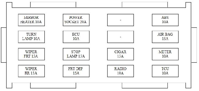
| Pozycja | Amperaż [A] | Chroniony obwód / funkcja |
|---|---|---|
| F1 | 10 | ABS control module |
| F2 | 15 | AIR BAG – SRS airbag control module |
| F3 | 10 | METER – Instrument cluster, speed sensor, ETACS module and warning circuits |
| F4 | 10 | TCU – Daytime running light module and TCU, depending on equipment |
| F5 | 20 | Function not specified in the available Carens FJ circuit listing. Position F5 is shown with a 20 A rating but no assigned circuit; confirm the cover legend before inserting a fuse |
| F6 | 15 | CIGAR – 12 V cigarette lighter and accessory-socket relay supply |
| F7 | 10 | RADIO – Audio unit, clock, ETACS and exterior mirror controls |
| F8 | 20 | POWER SOCKET – Additional 12 V power outlet |
| F9 | 10 | ECU – Diagnostic connector and engine control unit circuit |
| F10 | 15 | STOP LAMP – Brake lights |
| F11 | 15 | FRT DEF – Heated windscreen wiper parking area |
| F12 | 10 | MIRROR HEATER – Heated exterior mirrors |
| F13 | 10 | TURN LAMP – Turn signals and hazard warning circuit |
| F14 | 15 | WIPER FRT – Front wipers, washer and rain sensor where fitted |
| F15 | 15 | WIPER RR – Rear window wiper and washer |
Additional relays behind the dashboard
The relay positions shown below refer to the early FJ relay carrier. Equipment and market variations may leave some sockets empty. A relay is not rated in amperes in this table because these values describe fuse ratings rather than relay contact ratings.
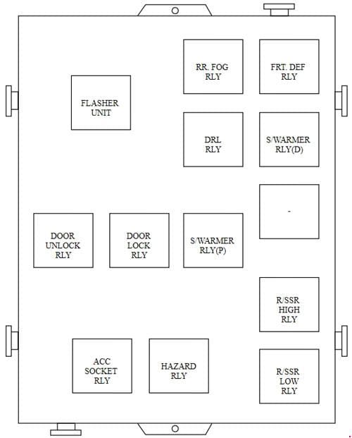
| Pozycja | Amperaż [A] | Chroniony obwód / funkcja |
|---|---|---|
| R1 | – | Turn signal flasher relay |
| R2 | – | Rear fog lamp relay |
| R3 | – | Front windscreen wiper de-icer relay |
| R4 | – | Heated seat relay |
| R5 | – | Daytime running light relay |
| R6 | – | Central locking unlock relay |
| R7 | – | Central locking lock relay |
| R8 | – | Second heated seat relay |
| R12 | – | Cigarette lighter relay |
| R13 | – | Hazard warning flasher relay |
Diesel high-current fuses – alternator and heaters
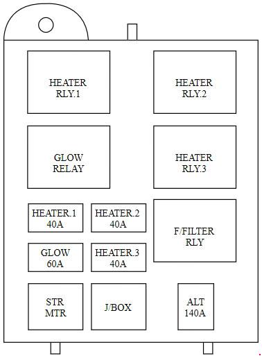
| Pozycja | Amperaż [A] | Chroniony obwód / funkcja |
|---|---|---|
| ALT | 140 | Alternator main high-current fusible link |
| GLOW | 60 | Diesel glow plug relay |
| HEATER.1 | 40 | First electric cabin auxiliary-heater circuit |
| HEATER.2 | 40 | Second electric cabin auxiliary-heater circuit |
| HEATER.3 | 40 | Third electric cabin auxiliary-heater circuit |
Which fuse should you check first?
12 V sockets: A dead cigarette lighter points first to CIGAR / F6 (15 A). The separate power socket is protected by POWER SOCKET / F8 (20 A), so one outlet may work while the other does not. Check the outlet itself if the correct fuse is intact.
Lights and wipers: If brake lights fail, check STOP LAMP / F10 (15 A). The front wiper circuit is F14 (15 A), while the rear wiper is F15 (15 A). A failed rear wiper can also be caused by damaged wiring in the tailgate hinge area.
Engine starting and cabin heating: For fuel-pump supply issues, check F/PUMP (10 A) in the engine box and the pump relay. Rear-window heating uses RR DEF (30 A). Weak or absent blower operation points to BLOWER (30 A), the blower motor and its controls. On diesel cars, poor cold starting can involve GLOW (60 A) or the glow-plug circuit.
Production and equipment differences
The Carens FJ fuse arrangement depends on engine type, market and installed equipment. In particular, the unused or undocumented F5 function must not be assumed from a later Kia circuit list. The third-generation Carens and later Rondo/Carens variants use a different distribution system. Before replacing a fuse, compare the rating and printed legend with the actual vehicle; do not substitute a higher-rated fuse.
Technical basis: early Kia Carens FJ 2002-2006 fuse and relay layouts, petrol and diesel wiring variants and cover legends.