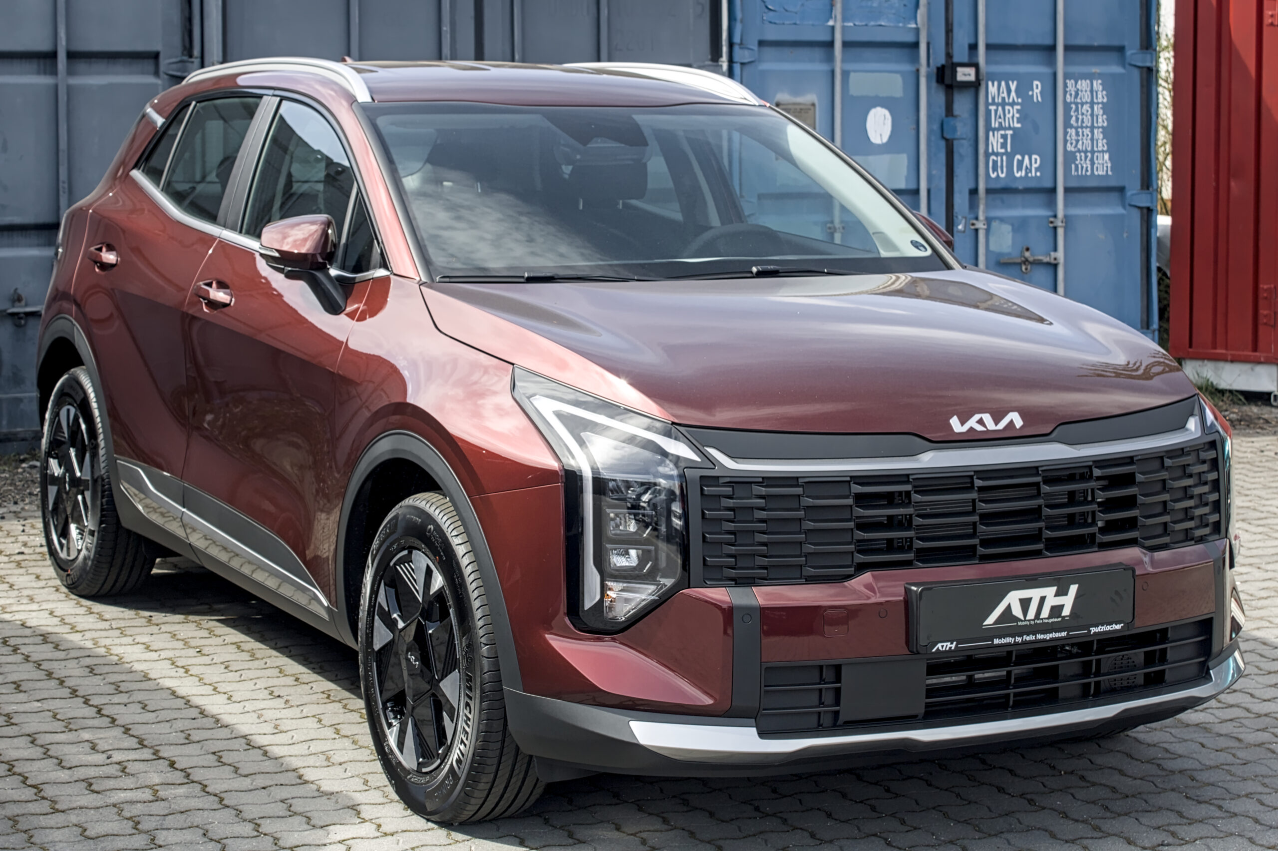
The 2025 Kia Sportage NQ5 has an ICU fuse panel on the driver’s side of the dashboard and a power distribution box in the engine compartment. The listings below preserve the fuse designations, ratings, protected circuits, PCB block entries and relays from the 2025 manufacturer’s documentation.
Engine and market coverage: these assignments describe the conventional combustion-engine layout. The Sportage Hybrid (HEV) and Plug-in Hybrid (PHEV) use additional high-voltage equipment and may have different fuse ratings or locations. Check the labels inside the covers of your actual vehicle before replacing a fuse.
Where are the fuse boxes on the 2025 Kia Sportage?
Cabin ICU panel: the fuse box is behind the removable trim cover at the lower/side section of the dashboard on the driver’s side. Switch the ignition off, release the cover carefully and read the fuse identification label on its reverse side.
Engine compartment: the main fuse and relay box is under the bonnet near the 12 V battery. Release the lid’s clips, locate the correct fuse or relay using the cover diagram and refit the lid securely after inspection.
Cabin ICU fuse panel
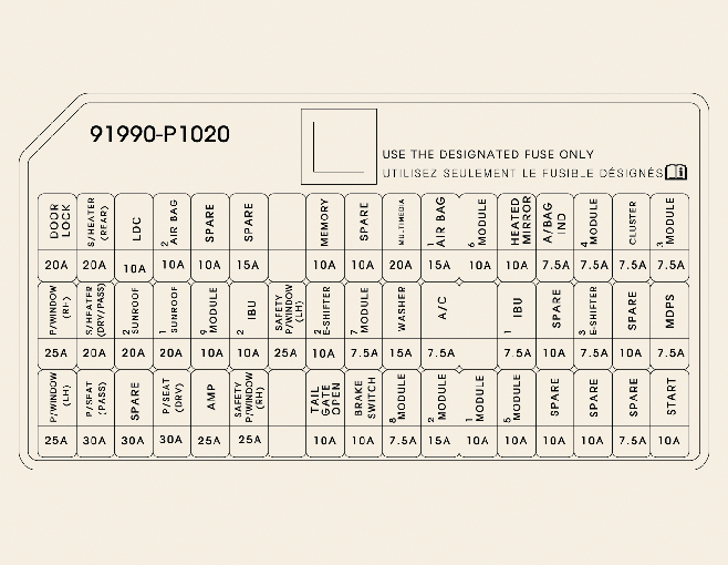
| Position | Amperage [A] | Protected circuit / function |
|---|---|---|
| DOOR LOCK | 20 | Central door locking and unlocking relay |
| P/WINDOW RH | 25 | Main power window switch and passenger window switch |
| P/WINDOW LH | 25 | Main power window switch |
| S/HEATER (REAR) | 20 | Rear heated seat module |
| S/HEATER (DRV/PASS) | 20 | Front heated and ventilated seats |
| P/SEAT (PASS) | 30 | Power passenger seat and seat relay module |
| SUNROOF2 | 20 | Sunroof sunshade motor control |
| AIRBAG2 | 10 | SRS control module |
| SUNROOF1 | 20 | Sunroof glass motor control |
| P/SEAT DRV | 30 | Power driver seat and Integrated Memory System (IMS) module |
| MODULE9 | 10 | Driver IMS, Smart Key door handles, rain sensor, hazard lamps, diagnostic connector and power tailgate |
| AMP | 25 | Audio amplifier |
| IBU2 | 10 | Integrated Body Control Unit (IBU), ignition switch and automatic transmission selector |
| P/WINDOW SAFETY RH | 25 | Passenger-side power window safety module |
| P/WINDOW SAFETY LH | 25 | Driver-side power window safety module |
| MEMORY | 10 | Power-folding mirrors, electric mirrors, instrument cluster, HVAC, ambient lighting, parking module and 450 W low-voltage DC/DC converter |
| LIFTGATE | 10 | Tailgate relay |
| MODULE7 | 7.5 | Integrated Body Control Unit (IBU) |
| BRAKE SWITCH | 10 | Brake lamp switch and IBU |
| MULTIMEDIA | 20 | Audio display, audio/video navigation unit and 200 W low-voltage DC/DC converter |
| WASHER | 15 | Multifunction switch, windshield washer |
| MODULE8 | 7.5 | Front seat ventilation and heating; left heated windshield relay |
| AIRBAG1 | 15 | SRS control module |
| A/C ON | 7.5 | PTC heater relay 1, blower relay and HVAC control units |
| MODULE2 | 15 | Front USB port and USB outlets near the driver and passenger seats |
| MODULE6 | 10 | Console switches, drive mode control, diagnostic connector and automatic transmission selector indicator |
| MODULE1 | 10 | Parking module, IBU, audio/navigation switches, mirror controls, amplifier, display, AVN unit and low-voltage DC/DC converter |
| HEATED MIRROR | 10 | Driver and passenger heated electric mirrors |
| IBU1 | 7.5 | Integrated Body Control Unit (IBU) |
| MODULE5 | 10 | Driver IMS, rear heated seats, front heated and ventilated seats, amplifier, multimedia, wireless charger, HVAC, auto-dimming mirror and low-voltage DC/DC converter |
| AIRBAG IND | 7.5 | Instrument cluster SRS warning indicator |
| MODULE4 | 7.5 | IBU, front camera, dashboard switches, parking module, front and rear corner radars, clutch sensor, AWD ECU and headlamps |
| E-SHIFTER3 | 7.5 | Shift Control Unit (SCU) and electronic automatic transmission selector |
| CLUSTER | 7.5 | Instrument cluster |
| MODULE3 | 7.5 | Brake lamp switch and overhead console |
| MDPS | 7.5 | Motor Driven Power Steering (MDPS) module |
| START | 10 | Alarm relay, transmission range sensor, PCM, IBU, ignition switch and starter relay |
| LDC | 10 | Low-voltage DC/DC converter, AVN, instrument cluster, wireless charger, HVAC, parking module and rear corner radars |
Engine compartment fuse and relay box
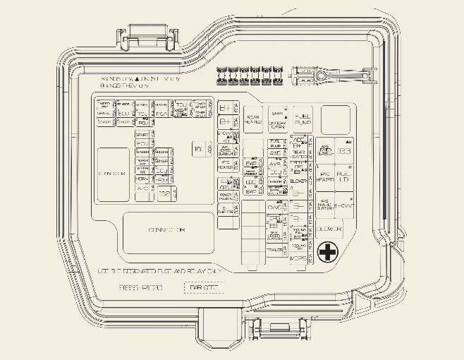
| Position | Amperage [A] | Protected circuit / function |
|---|---|---|
| MDPS1 | 80 | MULTI FUSE-1: Motor Driven Power Steering (MDPS) module |
| COOLING FAN2 | 60 | MULTI FUSE-1: Cooling fan controller |
| B+3 | 60 | MULTI FUSE-1: ICU circuits for rear seat heating, passenger seat, sunroof, driver seat, amplifier, power windows and main window relay |
| B+5 | 60 | MULTI FUSE-1: PCB block feeds for IG1, IG2, horn, HVAC, alarm, ECU2, main engine relay and main windshield wiper relay |
| B+4 | 50 | MULTI FUSE-1: ICU circuits for central locking, front seat heating/ventilation, AIRBAG2, MODULE9, IBU2, driver safety window, E-SHIFTER2, liftgate, brake switch and memory |
| BLOWER | 40 | MULTI FUSE-1: Blower relay |
| ABS1/EPB1 | 40 | MULTI FUSE-1: Electronic Stability Program (ESP) control unit |
| REAR HEATED | 40 | MULTI FUSE-1: Rear window defogger relay |
| ABS2 | 30 | MULTI FUSE-1: Electronic Stability Program (ESP) control unit |
| TRAILER1 | 50 | Fuse block: Trailer wiring connector |
| COOLING FAN1 | 50 | Fuse block: High-speed cooling fan relay |
| EPB2 | 60 | Fuse block: Electronic Stability Program (ESP) control unit |
| W/S HEATED GLASS RH | 50 | Fuse block: Right heated windshield relay |
| ECU5 | 10 | Fuse block: Not used |
| AMS | 10 | Fuse block: Battery sensor |
| AWD | 20 | Fuse block: AWD control module (ECM) |
| FUEL PUMP | 20 | Fuse block: Fuel pump relay |
| A/C ON1 | 10 | Fuse block: Blower relay and HVAC control module |
| E-SHIFTER1 | 30 | Fuse block: Shift Control Unit (SCU) |
| LIFTGATE | 40 | Fuse block: Power tailgate module |
| EOP | 40 | Fuse block: Electric oil pump |
| PTC HEATER3 | 50 | Fuse block: Fuel filter heater relay |
| W/S HEATED GLASS LH | 50 | Fuse block: Low cooling fan speed on certain versions; DCU relay, depending on specification |
| E-CVVT | 50 | Fuse block: Diesel: PTC heater 2 relay. Theta gasoline engine: E-CVVT relay; depends on version |
| B+2 | 50 | Fuse block: ICU circuits IPS06-IPS11 |
| B+1 | 60 | Fuse block: ICU circuits IPS01-IPS05 |
| IG2 | 40 | PCB block: IG2 relay |
| IG1 | 40 | PCB block: IG1 and ACC relays |
| FR WIPER2 | 7.5 | PCB block: Low-speed windshield wiper relay and IBU |
| SENSOR1 | 20 | PCB block: Ignition coils 1-4 |
| SENSOR7 | 10 | PCB block: Electric oil pump |
| ECU3 | 10 | PCB block: Powertrain Control Module (PCM) |
| SENSOR5 | 10 | PCB block: Fuel pump relay and oil level sensor |
| TCU2 | 10 | PCB block: Not used |
| TCU3 | 10 | PCB block: Not used |
| SENSOR3 | 20 | PCB block: Not used |
| ECU1 | 20 | PCB block: Powertrain Control Module (PCM) |
| SENSOR2 | 15 | PCB block: Upstream and downstream oxygen sensors |
| FR WIPER1 | 30 | PCB block: Main and low-speed wiper relays |
| RR WIPER | 15 | PCB block: Main wiper relay and rear wiper relay in ICU |
| HORN | 15 | PCB block: Horn relay |
| A/C ON2 | 10 | PCB block: Air-conditioning compressor relay |
| FCA | 10 | PCB block: Front radar |
| SENSOR4 | 10 | PCB block: Oil control valve no. 2, purge valve, variable oil pump, variable intake, fan controller and A/C compressor relay |
| SENSOR6 | 15 | PCB block: Fuel injectors 1-4 |
| ECU2 | 15 | PCB block: Powertrain Control Module (PCM) |
| TCU1 | 15 | PCB block: Powertrain Control Module (PCM) |
| ABS3/EPB3 | 7.5 | PCB block: Electronic Stability Program (ESP) control unit |
| POWER OUTLET2 | 20 | PCB block: Front 12 V power socket |
| POWER OUTLET1 | 20 | PCB block: Luggage compartment 12 V power socket |
| REAR HEATED | – | Micro relay: Rear window defogger |
| START | – | Micro relay: Starter motor |
| FUEL PUMP | – | Micro relay: Fuel pump |
| W/S HEATED LH | – | Micro relay: Heated windshield, left side |
| PTC HEATER 1 | – | Micro relay: PTC heater 1 |
| W/S HEATED RH | – | Micro relay: Heated windshield, right side |
| E-CVVT | – | Micro relay: E-CVVT, Theta engine |
| BLOWER | – | Micro relay: Cabin blower |
The 2025 Sportage shares vehicle architecture with the contemporary Hyundai Tucson NX4 2025, but their control modules and fuse assignments differ. Use the diagram for the exact model, year and drivetrain.
12 V sockets, USB chargers and multimedia
The front 12 V power outlet is protected by POWER OUTLET2 (20 A) in the under-hood PCB block. The luggage compartment socket uses POWER OUTLET1 (20 A). USB sockets use cabin MODULE2 (15 A). Multimedia uses a separate cabin MULTIMEDIA fuse (20 A), and the audio amplifier is protected by AMP (25 A).
What should be checked after an electrical failure?
If a replacement fuse blows again, do not fit a higher-rated fuse. For a non-working power socket, disconnect accessories and inspect the socket contacts. Wiper problems can also arise from the linkage or motor. When trailer lighting fails, inspect the towing connector, wiring and trailer module. The AWD system has a separately designated AWD fuse (20 A) for its control unit.
2025 Kia Sportage NQ5 fuse box FAQ
Which fuse powers the front 12 V outlet?
POWER OUTLET2, rated 20 A, in the engine compartment PCB fuse block. POWER OUTLET1 (20 A) supplies the luggage compartment outlet.
Where is the front heated seat fuse?
Inside the cabin ICU panel, S/HEATER (DRV/PASS) is a 20 A fuse. Seat ventilation and other seat-related functions may also use additional circuits depending on equipment.
Are the HEV and PHEV fuse layouts the same?
Do not assume so. Hybrid versions have separate high-voltage electrical components and different equipment; this table covers the conventional engine configuration shown in the source manual.
Where can I find the engine-bay fuse box?
Under the bonnet near the battery. Its cover has securing clips and a fuse label corresponding to the individual vehicle specification.