
Land Rover Discovery III, also sold as the LR3 (L319, 2004-2009), has main fuse boxes in the engine compartment and behind the passenger glovebox. Factory towing equipment adds trailer protection circuits, while specially armoured models may have a separate panel in the centre console. The complete tables below preserve unoccupied locations and petrol versus 2.7 TDV6 diesel assignments. Repeated position numbers indicate alternative versions, not two fuses fitted to one socket simultaneously.
Where are the Discovery III fuse boxes?
Under the bonnet: Switch off the ignition and raise the bonnet. At the rear of the engine compartment, locate the protective cover near the scuttle. Press the two front catches, lift its edge and slide the cover forward to remove it. Open the plastic lid of the main fuse box underneath. The assembly also contains relays R1-R19 and high-current fusible links FL1-FL20. These are distinct from the 30 numbered fuse locations listed below, and their replacement should be handled by a workshop.
Passenger compartment: Open the passenger glovebox, gently squeeze the upper retaining stops inward and lower the glovebox towards the floor. The numbered fuse panel 1-69 is behind it. Check the fuse legend attached to the glovebox. Use a suitable plastic fuse puller.
Trailer and special equipment: Factory towing equipment may have additional fuses close to the trailer wiring in the rear of the vehicle. Check the trim location in the handbook for the fitted towbar system. Only a purpose-built armoured Discovery III has the satellite fuse panel in the centre console: remove the CD holder, compartment floor and transparent cover to access it.
Engine compartment – fuses 1-30, with engine variants
Fuse functions 6, 10, 13 and 17 vary between petrol and diesel. From the 2007 model year, the diesel assignment for position 6 includes engine sensors and glow-plug relay control, while petrol models use the same number for ignition coils. Select the line matching the vehicle’s engine and model year.
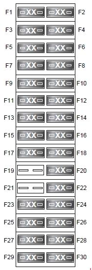
| Pozycja | Amperaż [A] | Chroniony obwód / funkcja |
|---|---|---|
| 1 | 25 | Fuel pump |
| 2 | – | Unused position or no assigned circuit in this configuration |
| 3 | 5 | Air suspension control module (ECU) |
| 4 | 25 | Diesel – engine management system (EMS), engine ECU and fuel pump relay control |
| 5 | 10 | Petrol – engine management (EVAP purge valve, EGR and intake manifold tuning valve); electronics-box cooling fan |
| 6 | 15 | Petrol – engine management ignition coils |
| 6 | 15 | From 2007 model year: diesel engine management sensors and glow-plug relay control |
| 7 | 25 | Front heated seats |
| 8 | 25 | Rear heated seats |
| 9 | 15 | Up to 2005 model year: active roll control |
| 10 | 15 | Petrol – engine management (throttle motor, mass airflow sensor) and cooling fan |
| 10 | 15 | Diesel – cooling fan |
| 11 | 15 | Petrol – engine management, rear oxygen sensors |
| 12 | 10 | Heated windscreen washer jets |
| 13 | 10 | Petrol – engine management ECU, variable valve timing (VVT) and fuel pump relay control |
| 13 | 10 | Diesel – engine management PCV and VCV control valves |
| 14 | 20 | Petrol – engine management, front oxygen sensors |
| 15 | 30 | Heated windscreen |
| 16 | 10 | Heated exterior mirrors |
| 17 | 15 | Petrol – engine management, fuel injectors |
| 17 | 15 | Diesel – engine management (MAF, EGR) and electronics-box cooling fan |
| 18 | 30 | Heated windscreen, second circuit |
| 19 | – | Unused position or no assigned circuit in this configuration |
| 20 | 5 | Alternator |
| 21 | – | Unused position or no assigned circuit in this configuration |
| 22 | 30 | Rear ventilation blower |
| 23 | 25 | Dynamic Stability Control (DSC) |
| 24 | 20 | Petrol – brake assist vacuum pump |
| 25 | 10 | Lighting switch |
| 26 | 20 | Air suspension control module (ECU) |
| 27 | 5 | Engine control module (ECM) |
| 28 | 20 | Diesel – auxiliary heater |
| 29 | 30 | Front windscreen wipers |
| 30 | 10 | Automatic transmission control module |
Passenger compartment – fuses 1-69
This panel covers exterior and interior lights, windows, seats, sockets, Terrain Response, audio and the electric parking brake. Fuse 11 for the washer pump is listed at 15 A or 10 A in the 2005 handbook variant. These are separate vehicle specifications, not interchangeable fuse ratings.
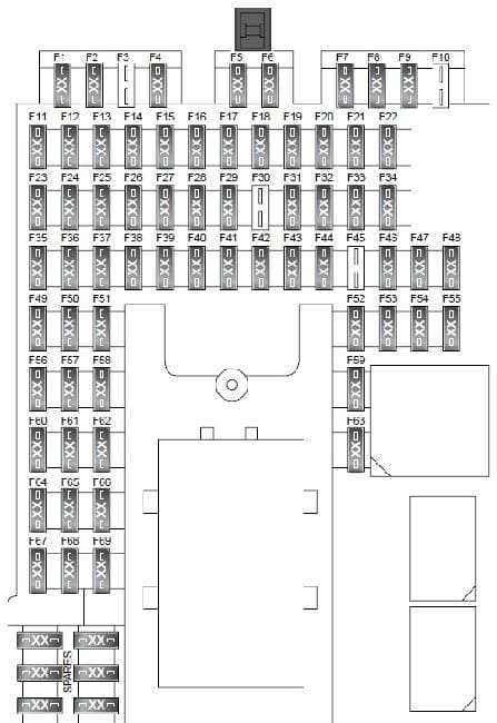
| Pozycja | Amperaż [A] | Chroniony obwód / funkcja |
|---|---|---|
| 1 | 10 | Interior lamps: glovebox, sun visor vanity mirrors, map and roof lamps; electric seats without memory |
| 2 | 10 | Right-hand position lamps |
| 3 | 10 | Up to 2005 model year: ambient interior lighting |
| 4 | 10 | Left-hand position lamps |
| 5 | 10 | Reversing lamps |
| 6 | 10 | Trailer reversing lamp |
| 7 | 25 | Driver’s electric window |
| 8 | 30 | Trailer connector, permanent battery supply |
| 9 | 5 | SRS airbag system; 2007-onward listing identifies the airbags explicitly |
| 10 | – | Unused position or no assigned circuit in this configuration |
| 11 | 15 / 10 | Windscreen washer pump; 15 A in one arrangement, 10 A in the 2005 handbook version. Verify the vehicle-specific rating |
| 12 | 15 | Horn |
| 13 | 25 | Heated rear window |
| 14 | 10 | Trailer position lamps |
| 15 | 15 | Brake lamps and brake pedal switch |
| 16 | 10 | Power-folding mirror circuit |
| 17 | 20 | Rear right electric window |
| 18 | 5 | Rain sensor and ambient light sensor |
| 19 | 15 | Second-row 12 V accessory power outlet |
| 20 | 15 | Sunroof |
| 21 | 25 | Front passenger electric window |
| 22 | 10 | Trailer connector, ignition-switched supply |
| 23 | – | Unused position or no assigned circuit in this configuration |
| 24 | 5 | Transfer case, centre differential and Terrain Response system |
| 25 | 5 | Engine control module (ECM) |
| 26 | 5 | Battery-backed alarm sounder |
| 27 | 10 | Adaptive front lighting and headlamp levelling |
| 28 | 5 | Engine compartment fuse box ignition feed |
| 29 | 30 | Front passenger power seat |
| 30 | – | Unused position or no assigned circuit in this configuration |
| 31 | 20 | Rear left electric window |
| 32 | 15 | Rear fog lamps |
| 33 | 5 | Door mirror adjustment, automatic gearbox selector and passenger electric seat circuit, up to 2005 where fitted |
| 34 | 15 | Front-row 12 V accessory power outlet |
| 35 | 5 | Air suspension control module (ECU) |
| 36 | 5 | Parking sensors and tyre pressure monitoring system (TPMS) |
| 37 | 5 | Dynamic Stability Control (DSC) |
| 38 | 15 | Front fog lamps |
| 39 | 5 | Instrument cluster |
| 40 | 5 | Ignition key-in detection switch |
| 41 | 5 | Electric parking brake (EPB) |
| 42 | 30 | Audio amplifier |
| 43 | 10 | Radio-frequency receiver and tyre pressure monitoring |
| 44 | 5 | Automatic transmission selector |
| 45 | – | Unused position or no assigned circuit in this configuration |
| 46 | 30 | Driver’s power seat |
| 47 | 15 | Third-row 12 V accessory power outlet |
| 48 | 15 | Rear window wiper |
| 49 | 30 | Central door locking |
| 50 | 10 | Fuel filler flap release actuator |
| 51 | 10 | Climate control ECU |
| 52 | 5 | Telephone and traffic information centre |
| 53 | 15 | Multimedia module, audio head unit and DVD player |
| 54 | 5 | Electric seat memory and lumbar pump |
| 55 | 15 | 12 V cigarette lighter |
| 56 | 10 | Adaptive front lighting, left-hand unit |
| 57 | 10 | Rear-seat entertainment module |
| 58 | 10 | Telephone, touchscreen, multimedia module and TV tuner |
| 59 | 10 | Cooled centre console cubby box |
| 60 | 5 | Engine control module (ECM) |
| 61 | 10 | Adaptive front lighting, right-hand unit |
| 62 | 5 | Dipped beam and exterior lamps |
| 63 | 10 | Diagnostic socket |
| 64 | 5 | Automatic transmission control unit |
| 65 | – | Unused position or no assigned circuit in this configuration |
| 66 | 5 | Hill Descent Control (HDC) switch, brake switch, steering angle sensor and DSC switch |
| 67 | 5 | Exterior lighting |
| 68 | 5 | Instrument cluster |
| 69 | 5 | Automatic-dimming interior mirror and, on models up to 2005, electrochromic mirror / HomeLink equipment |
Trailer wiring fuse box – positions 1-6
These extra circuits are fitted only with the relevant towing installation and protect the trailer lighting and electrical feeds. Compare the equipment and its own fuse cover before removing trim.
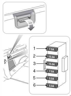
| Pozycja | Amperaż [A] | Chroniony obwód / funkcja |
|---|---|---|
| 1 | 7.5 | Trailer brake lights |
| 2 | 15 | Ignition-switched trailer feed |
| 3 | 15 | Trailer permanent battery feed |
| 4 | 7.5 | Trailer rear fog lamps |
| 5 | 5 | Right-hand trailer tail lamp |
| 6 | 5 | Trailer number plate and left tail lamp |
Armoured version – satellite fuse panel 1-6
This additional panel is exclusive to specialist armoured vehicles; it is not part of the standard LR3 / Discovery III electrical layout.

| Pozycja | Amperaż [A] | Chroniony obwód / funkcja |
|---|---|---|
| 1 | 5 | Intercom |
| 2 | 20 | Siren |
| 3 | 5 | Discreet service lighting, armoured version only |
| 4 | 10 | Warning / signalling lamp, armoured version only |
| 5 | 3 | Battery state monitor |
| 6 | 30 | Additional special-purpose equipment |
Petrol, diesel and model-year differences
A fuse number can have different functions between petrol and 2.7 TDV6 diesel versions. In the engine-bay box, the variable assignments especially affect positions 6, 10, 13 and 17. Equipment, market and production changes also influence the cabin fuse occupation. Use the vehicle handbook and the physical cover diagram rather than assuming every 2004-2009 Discovery III uses precisely the same circuit allocation.
Practical checks for electrical faults
Cigarette lighter and 12 V outlets: The lighter uses passenger fuse 55 (15 A). The accessory sockets are separately protected: fuse 34 for the front row, fuse 19 for the second row and fuse 47 for the third row, all 15 A. Test the actual socket contacts if the fuse is intact.
Wipers: For a failed front wiper, start with engine-bay fuse 29 (30 A). The rear wiper is passenger-compartment fuse 48 (15 A).
Air suspension and Terrain Response: The air suspension module receives supplies through engine fuses 3 (5 A) and 26 (20 A), and cabin fuse 35 (5 A). Terrain Response and the centre differential also involve cabin fuse 24 (5 A). Fuse checks are only an initial diagnostic step; read stored fault codes when the system reports a suspension or drivetrain fault.
Related Discovery generation
The successor Land Rover Discovery IV / LR4 (2009-2016) retains the L319 family name but has substantially revised fuse assignments and extra electronics. Do not substitute Discovery III diagrams for those of the newer generation.
Technical reference: Land Rover, “Discovery 3 Owner’s Handbook”, publication LRL 21 02 53 502 (2005), with additional later model-year variants identified where applicable.