
The early Rover 75 (R40) uses a 42-position fuse panel behind the passenger glovebox and a separate 10-position fuse box in the engine compartment. This guide covers the original 1999-2002 electrical arrangement, including unoccupied positions and petrol/diesel differences. MG Rover revised the passenger fuse carrier in early 2003, so these diagrams must not be applied to later cars without checking the panel and VIN.
Fuse box locations and access
Passenger compartment: Switch off the ignition and open the passenger door. The main fuse panel is behind the glovebox, not next to the steering column. Locate the lower access cover, release its fastener with a coin or small flat-bladed screwdriver, remove the trim and press the two catches on the fuse-box cover. The numbered fuses are arranged as shown below.
Engine compartment: Open the bonnet. The engine fuse box is on the left-hand side of the engine bay when viewed in the direction of travel. Press the catch and hinge the cover open. Check the legend on your vehicle, particularly for the engine-specific positions. The separate high-current fusible links are not part of the ten numbered fuses in the table and are intended for service inspection.
Passenger compartment – fuses 1-42
The original 42-position layout is shown immediately above the complete table. Empty positions and the rated-but-unoccupied position 42 have not been omitted.
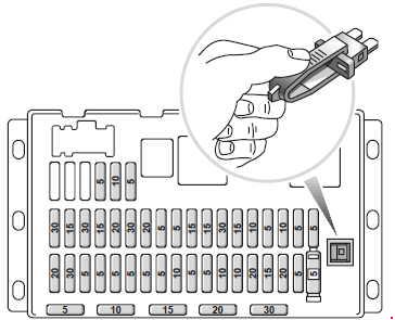
| Pozycja | Amperaż [A] | Chroniony obwód / funkcja |
|---|---|---|
| 1 | 20 | Rear electric windows |
| 2 | 30 | Traction control system, where fitted |
| 3 | 5 | Seat position memory and clock |
| 4 | 5 | Air conditioning system and electric window controls |
| 5 | 5 | Body Control Unit (BCU) and windscreen wiper control |
| 6 | 5 | Instrument cluster |
| 7 | 5 | Immobiliser and cruise control |
| 8 | 5 | Body Control Unit (BCU), additional supply |
| 9 | 10 | Windscreen washer pump |
| 10 | 5 | Instrument cluster, secondary circuit |
| 11 | 5 | Audio system, window and mirror controls, and cigarette-lighter circuit |
| 12 | 10 | Accessory socket, electric rear-window blind and parking sensors, where fitted |
| 13 | 10 | Interior lighting |
| 14 | 20 | Central door locking |
| 15 | 15 | Cigarette lighter / 12 V socket |
| 16 | 20 | Additional 12 V accessory socket |
| 17 | 5 | Instrument cluster, immobiliser and automatic temperature control (ATC) |
| 18 | 5 | SRS airbag system, circuit marked with a yellow surround |
| 19 | 30 | Driver’s electrically adjustable seat |
| 20 | 20 | Fuel pump |
| 21 | 30 | Electric seat adjustment |
| 22 | 15 | Factory audio amplifier |
| 23 | 20 | Electric sunroof, where fitted |
| 24 | 30 | Front electric windows |
| 25 | 20 | Heated seats, where fitted |
| 26 | 5 | Anti-theft alarm and immobiliser |
| 27 | 5 | Instrument cluster, additional circuit |
| 28 | 15 | Horn |
| 29 | 15 | Rear window wiper on the Tourer / estate version |
| 30 | 30 | Headlamp washers, where fitted |
| 31 | 15 | Factory alarm siren |
| 32 | 10 | ABS and traction control electronics |
| 33 | 5 | Driver’s seat-belt warning and automatic climate control |
| 34 | 10 | Engine management control supply |
| 35 | 5 | Heated door mirrors and heated washer jets |
| 36 | 5 | Alternator control circuit |
| 37 | – | Unused position in this early fuse panel |
| 38 | – | Unused position in this early fuse panel |
| 39 | – | Unused position in this early fuse panel |
| 40 | 5 | Exterior lighting |
| 41 | 10 | Cruise control and reversing lamps |
| 42 | 5 | Unoccupied in this configuration; handbook lists a nominal 5 A rating |
Engine compartment – fuses 1-10
The listed functions distinguish petrol and diesel applications. High-current fusible links housed separately from this block are not included in its ten numbered positions.
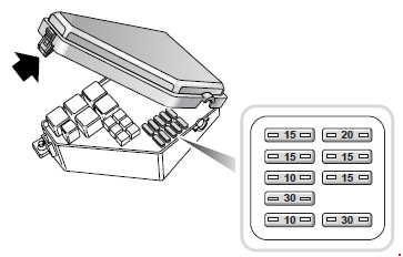
| Pozycja | Amperaż [A] | Chroniony obwód / funkcja |
|---|---|---|
| 1 | 15 | Diesel: EGR, injection pump and fuel-pressure regulation; petrol: oxygen sensors; all engines: powertrain management |
| 2 | 20 | Petrol: ignition coils; all engines: engine management electronics |
| 3 | 15 | Petrol: camshaft sensor and oxygen sensors |
| 4 | 15 | Automatic transmission, air conditioning and cooling fan; diesel cruise control where fitted |
| 5 | 10 | Petrol engine management, additional circuit |
| 6 | 15 | Front fog lamps |
| 7 | 30 | ABS pump and power supply |
| 8 | 15 | Diesel fuel-fired auxiliary heater, where fitted |
| 9 | 10 | Air conditioning system |
| 10 | 30 | Front windscreen wiper and washer circuits |
Practical checks for common electrical faults
In the early Rover 75, the cigarette lighter is protected by passenger-compartment fuse 15 (15 A), while the separate accessory outlet uses fuse 16 (20 A). If central locking is inoperative, check fuse 14 (20 A); the horn uses fuse 28 (15 A). The Tourer rear wiper has its own fuse 29 (15 A). A non-operating fuel pump points to cabin fuse 20 (20 A). If the engine cranks but does not start, the relevant engine-management feeds under the bonnet include positions 1, 2 and 5, depending on engine type. For failed front wipers, check engine-bay fuse 10 (30 A) and the BCU-related cabin fuse 5 (5 A).
Important fuse box changes from early 2003
In January 2003, MG Rover introduced a modular, hard-wired passenger fuse box using mini fuses. The wiring and fuse locations changed. In particular, the earlier 42-position layout is not a universal diagram for every Rover 75 built through 2005. Identify the actual panel and check the vehicle’s build date and VIN; the documented change is associated with VIN 279844 onwards.
Related MG Rover model
The closely related MG ZT (2001-2002) fuse box guide covers the sporty model built on the same R40 architecture. The arrangement is similar in early cars, but engine and equipment variations still matter.
Technical reference: Rover Group, Rover Seventy Five Owner’s Handbook, issue 3, publication RCL 0306ENG (1999), "Fuses", pp. 174-178. Information applies to the original early-type fuse carrier.