
The facelift Peugeot 207 (2009-2012) has its passenger fuse board at the lower dashboard and the engine distribution box beside the battery. The 2011 handbook lists additional G39 and G40 circuits and two distinct high-current Maxi sections. The tables below preserve every one of the 48 physical fuse and shunt positions in this specific installation. They also retain unused sockets and the engine-equipment differences between petrol 1.4/1.6, 1.6 THP and HDi. Do not substitute the retractable-roof fuse allocations from the 207 CC.
Fuse box location and access
With the ignition switched off, open the lower left-hand dashboard access cover. The 2011 Peugeot owner handbook instructs owners to open the glovebox, release its retaining guide and unclip the fuse cover from the top to access the puller; trim can vary between steering configurations. Under the bonnet the other fuse carrier is covered next to the battery. Unclip its lid, inspect the F1-F18 labels and refit the weather seal completely. Maxi power links in the same engine distribution area should be serviced by a qualified technician, not treated as standard blade fuses.
Additional G39 and G40 positions
The Peugeot 207 2011 handbook labels G39 as unused, even though the rating column contains a nominal 20 A. G40 at 20 A feeds optional heated front seats. This is not the CC’s G37 retractable roof supply or its alternative G39 assignments.
| Pozycja | Amperaż [A] | Chroniony obwód / funkcja |
|---|---|---|
| G39 | 20 | Unused nominal 20 A position in the 2011 handbook |
| G40 | 20 | Optional heated front seats for driver and passenger |
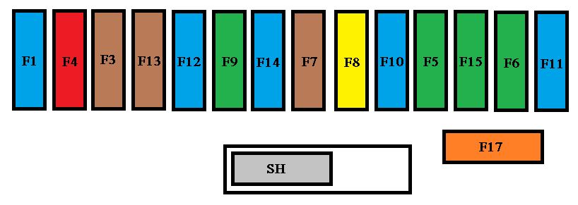
Passenger-compartment fuses F1-F17 and PARC shunt
Cabin F1 15 A operates the rear wiper; F3 5 A protects the airbag ECU, F6 30 A front windows and folding mirrors, F8 20 A radio and driver controls, F9 30 A the front 12 V outlet and the rear socket on SW models, and F17 40 A the heated rear screen and wing mirrors. F2 and F10 are unused. SH is a PARC transport-mode shunt rather than a standard current-rated fuse.
| Pozycja | Amperaż [A] | Chroniony obwód / funkcja |
|---|---|---|
| F1 | 15 | Rear window wiper |
| F2 | – | Unused position |
| F3 | 5 | Airbag and pyrotechnic seatbelt pretensioner ECU |
| F4 | 10 | Clutch switch, OBD connector, electrochromic mirror, A/C, steering angle sensor and diesel particulate-filter pump |
| F5 | 30 | Electric windows, rear one-touch windows and SW panoramic shade |
| F6 | 30 | Front one-touch windows and electric folding mirrors |
| F7 | 5 | Courtesy and reading lights, vanity and glovebox lights |
| F8 | 20 | Radio/telephone, multifunction display, clock, steering-wheel switches and trailer module |
| F9 | 30 | Front 12 V outlet; rear SW socket where equipped |
| F10 | 15 | Unused in this 2011 version |
| F11 | 15 | Diagnostic socket, low-current ignition supply and automatic transmission control |
| F12 | 15 | Rain/light sensor, amplifier, trailer module and driving-school equipment |
| F13 | 5 | Engine fuse box control, ABS relay and dual brake switch |
| F14 | 15 | Instruments, seatbelt indicators, headlamp adjustment, A/C, hands-free telephone, parking sensors and airbags |
| F15 | 30 | Central locking and deadlocking |
| F17 | 40 | Heated rear window and wing mirrors |
| SH | Shunt | PARC transport-mode shunt; not a normal replaceable fuse |
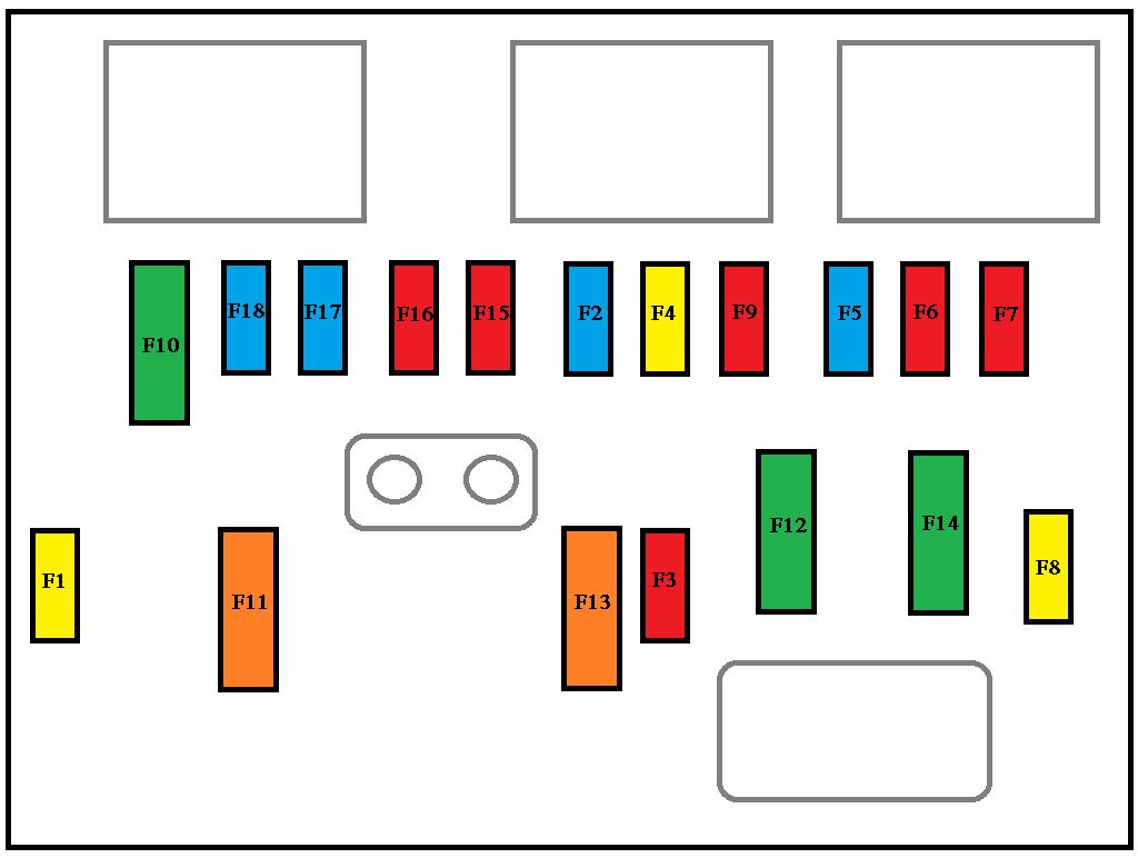
Engine bay fuses F1-F18
The engine F2 15 A protects the horn, F3 10 A window washers, F4 20 A headlamp washers when equipped, F8 25 A the starter control, F11 40 A the cabin blower, and F12 30 A the windscreen wipers. Engine management differs by powertrain: THP has turbo and timing-control solenoids while diesel HDi includes injection, EGR, preheating and particulate-filter equipment. A different 207 edition may use 20 A at F8, so compare the vehicle’s fuse label.
| Pozycja | Amperaż [A] | Chroniony obwód / funkcja |
|---|---|---|
| F1 | 20 | Engine ECU and radiator fan relays; THP timing/EVAP solenoids; HDi injection, EGR, intake and fuel sensors |
| F2 | 15 | Horn |
| F3 | 10 | Front and rear window washers |
| F4 | 20 | Headlamp washers if equipped |
| F5 | 15 | Petrol fuel pump or THP boost solenoids |
| F6 | 10 | Vehicle speed sensor and automatic gearbox |
| F7 | 10 | Electric power steering control and diesel protection module |
| F8 | 25 | Starter control – 25 A in this 2011 207 version; other editions may specify 20 A |
| F9 | 10 | ABS/ESP module and brake switch |
| F10 | 30 | Injection ECU actuators, coils, injectors, lambda probes, thermostat and diesel solenoids |
| F11 | 40 | Heater and air-conditioning blower motor |
| F12 | 30 | Front wipers, low/high speed |
| F13 | 40 | BSI power after ignition |
| F14 | 30 | Diesel preheating glow plugs |
| F15 | 10 | Left main-beam headlamp |
| F16 | 10 | Right main-beam headlamp |
| F17 | 15 | Left dipped-beam headlamp |
| F18 | 15 | Right dipped-beam headlamp |
High-current engine fuse box 1 – MF1-MF7
MF1 at 70 A protects the cooling fan. MF2 and MF3 use 20/30 A factory alternatives for ABS/ESP. MF4/MF5 are 60 A BSI supplies; MF6 30 A is an additional fan supply on equipped 1.6 THP engines; MF7 80 A powers the dashboard fuse carrier. Ratings are specific to the installed high-current carrier.
| Pozycja | Amperaż [A] | Chroniony obwód / funkcja |
|---|---|---|
| MF1 | 70 | Radiator cooling fan |
| MF2 | 20/30 | ABS/ESP hydraulic pump, 20/30 A depending on version |
| MF3 | 20/30 | ABS/ESP valve solenoids, 20/30 A depending on version |
| MF4 | 60 | BSI first main feed |
| MF5 | 60 | BSI second main feed |
| MF6 | 30 | Auxiliary radiator fan on 1.6 THP |
| MF7 | 80 | Dashboard fuse carrier main feed |
High-current engine fuse box 2 – MF8-MF11
The source lists MF8 as unassigned despite a nominal 30 A location. MF9 80 A protects diesel auxiliary heating, MF10 80 A the power steering pump and MF11 40 A the Valvetronic motor on 1.6 THP. The original source separates these into two engine sub-boxes. There is no independently confirmed large-scale Maxi diagram to add, so the engine F1-F18 drawing is not misrepresented as the Maxi layout.
| Pozycja | Amperaż [A] | Chroniony obwód / funkcja |
|---|---|---|
| MF8 | 30 | Unused MF8 slot in this version |
| MF9 | 80 | Diesel supplementary heater |
| MF10 | 80 | Electric power-steering pump high-current supply |
| MF11 | 40 | Valvetronic motor on fitted 1.6 THP petrol engines |
Common electrical faults
Rear wiper: Cabin F1 15 A, then inspect the wiring in the tailgate hinge. Rear demister or heated wing mirrors: Cabin F17 40 A, then inspect the rear-glass connectors and relay. Horn: Engine F2 15 A, relay and the horn assembly. Front 12 V socket: Cabin F9 30 A, socket contacts and any lodged metal object.
Starter does not crank: Verify whether the exact vehicle has engine F8 25 A as in this 2011 reference, then test the starter solenoid and engine earth. Steering assist warning: Engine F7 10 A is the control supply; MF10 80 A is the separate main pump feed. Do not increase a fuse rating or bridge a high-current link.
Other Peugeot fuse layouts
For the retractable hardtop use the separate Peugeot 207 CC (2006-2014) guide. The Peugeot 207 (2006-2008) has an earlier electrical configuration, while the Peugeot 308 I T7 has different fuse numbering.
Reference: Peugeot 207 2011 owner’s handbook, Practical Information, dashboard, engine and Maxi fuse tables. Check production configuration, engine and equipment before making an electrical repair.