
Peugeot 307 Break, also known as the 307 Kombi, is the conventional estate body of the T5 generation, introduced in 2002. This electrical reference separates the earliest 2002 panel from the revised 2003-2004 installations. It retains all 83 technical fuse and Maxi entries plus seven cross-reference rows, including the 2004 F27 airbag protection, unused positions and differences in BSI and cooling-fan supplies. The panoramic-roof SW has a related but distinct set of passenger circuits.
Fuse-box locations and access
Passenger panel: Switch the ignition off. In a left-hand-drive car the service flap is below the dashboard next to the steering column. Turn the retaining latch about a quarter-turn and lower the cover. The original puller and spare fuses are normally mounted inside. On right-hand-drive cars follow the corresponding passenger-side access instructions.
Engine panel: Lift the bonnet and locate the black fuse carrier beside the battery. Unclip the cover to access the F1-F18 blades and separate Maxi main feeds. The earliest 2002 and later 2003-2004 values must not be combined just because the fuse boxes have similar housings. Refit the cover to prevent water entry.
Commonly searched 307 Break fuses
These seven rows are a shortcut to the full tables. Cabin F2 for the rear wiper is not engine F2 for the fuel pump, and the front-wiper motor is on engine F17 rather than cabin F17.
| Pozycja | Amperaż [A] | Chroniony obwód / funkcja |
|---|---|---|
| F7 | 20 | 2002-2004 Break: front power outlet and lighter in cabin |
| F10 | 15 | 2002-2004 Break: rear 12 V socket in cabin |
| F2 | 15 | 2002-2004 Break: rear wiper in cabin |
| F26 | 30 | 2002-2004 Break: rear-window demister in cabin |
| F2 | 15 | 2002-2004 Break: fuel pump in ENGINE box |
| F13 | 15 | 2002-2004 Break: horn in ENGINE box |
| F17 | 30 | 2002-2004 Break: front wipers in ENGINE box |
Dashboard fuse box – 2002 Break
Cabin F7 (20 A) powers the front 12 V outlet, F10 (15 A) the rear outlet, and F2 (15 A) the tailgate wiper. F11 (15 A) supplies the audio/display equipment, F16 (5 A) the engine-box and safety electronics, and F26 (30 A) the heated rear glass. F19 is a PARC configuration shunt occupying a nominal 30 A holder, not a conventional fuse.
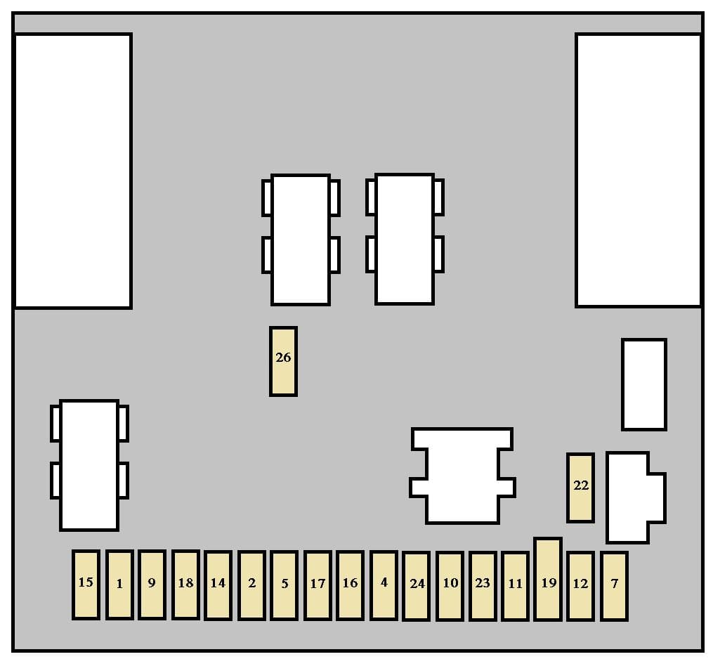
| Pozycja | Amperaż [A] | Chroniony obwód / funkcja |
|---|---|---|
| F1 | 10 | Rear fog lamp |
| F2 | 15 | Rear window wiper on the tailgate |
| F4 | 15 | Front electric windows and optional sunroof on the standard Break estate |
| F5 | 15 | Left rear stop lamp, including trailer stop-light circuit |
| F7 | 20 | Interior and reading lamps, glovebox light and front 12 V outlet (20 A in Break, unlike 30 A in the 2003-2004 panoramic SW) |
| F9 | 30 | Front electric windows, one-touch operation and optional sunroof |
| F10 | 15 | Diagnostic connector, rear 12 V power outlet and optional trailer wiring |
| F11 | 15 | Radio, multifunction display, steering-wheel controls and automatic gearbox |
| F12 | 10 | Right front and rear side lamps, registration-plate and trailer lighting, illuminated dashboard switches, A/C and cigarette-lighter illumination |
| F14 | 30 | Central locking and deadlocking |
| F15 | 30 | Rear electrically operated windows, including one-touch equipment on suitable models |
| F16 | 5 | Power feed to engine fuse box, alarm, diesel particulate filter, steering-wheel switches and airbags |
| F17 | 10 | Right rear stop lamp and high-mounted third brake light |
| F18 | 10 | Diagnostic connector, steering-wheel switches, brake and clutch switches, coolant-level switch and additional stop switch |
| F19 | Shunt (30 A slot) | PARC parking/transport configuration shunt (original table shows a 30 A holder), not an ordinary blade fuse |
| F22 | 10 | Left side lamps, registration-plate and trailer lighting |
| F23 | 15 | Factory alarm siren and passenger-compartment volumetric alarm sensors |
| F24 | 15 | Instrument cluster, audio system, multifunction display, air conditioning and optional parking/rain/light sensing |
| F26 | 30 | Heated rear window and demister supply |
Dashboard fuses – 2003-2004 Break
In the later first-phase installation F11 rises to 20 A, F16 to 10 A, and the 2004 manual adds F27 (10 A) for airbags at the top of the board. This Break source lists F7 at 20 A, unlike the 30 A front socket fuse described in the panoramic-roof SW manual. Use the vehicle’s exact body and fuse cover.
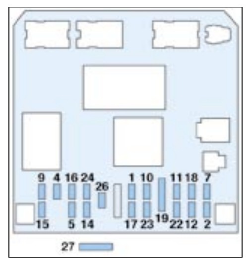
| Pozycja | Amperaż [A] | Chroniony obwód / funkcja |
|---|---|---|
| F1 | 10 | Rear fog lamp |
| F2 | 15 | Rear window wiper on the tailgate |
| F4 | 15 | Front electric windows and optional sunroof on the standard Break estate |
| F5 | 15 | Left rear stop lamp, including trailer stop-light circuit |
| F7 | 20 | Interior and reading lamps, glovebox light and front 12 V outlet (20 A in Break, unlike 30 A in the 2003-2004 panoramic SW) |
| F9 | 30 | Front electric windows, one-touch operation and optional sunroof |
| F10 | 15 | Diagnostic connector, rear 12 V power outlet and optional trailer wiring |
| F11 | 20 | Radio, multifunction display, steering-wheel controls and automatic gearbox |
| F12 | 10 | Right front and rear side lamps, registration-plate and trailer lighting, illuminated dashboard switches, A/C and cigarette-lighter illumination |
| F14 | 30 | Central locking and deadlocking |
| F15 | 30 | Rear electrically operated windows, including one-touch equipment on suitable models |
| F16 | 10 | Power feed to engine fuse box, alarm, diesel particulate filter, steering-wheel switches and airbags |
| F17 | 10 | Right rear stop lamp and high-mounted third brake light |
| F18 | 10 | Diagnostic connector, steering-wheel switches, brake and clutch switches, coolant-level switch and additional stop switch |
| F19 | Shunt (30 A slot) | PARC parking/transport configuration shunt (original table shows a 30 A holder), not an ordinary blade fuse |
| F22 | 10 | Left side lamps, registration-plate and trailer lighting |
| F23 | 15 | Factory alarm siren and passenger-compartment volumetric alarm sensors |
| F24 | 15 | Instrument cluster, audio system, multifunction display, air conditioning and optional parking/rain/light sensing and 2004 rain/brightness sensor |
| F26 | 30 | Heated rear window and demister supply |
| F27 | 10 | Supplementary airbag / SRS protection located above the dashboard fuse row |
Under-bonnet fuse box – 2002 Break
F2 (15 A) protects the petrol fuel pump, F13 (15 A) the horn, F17 (30 A) the front wipers, and F18 (40 A) the A/C blower. The earlier engine F7 (20 A) supplies headlamp washers, and F16 (40 A) protects an applicable petrol secondary-air pump. The original diagram below identifies the corresponding F1-F18 carrier.
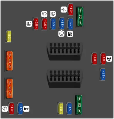
| Pozycja | Amperaż [A] | Chroniony obwód / funkcja |
|---|---|---|
| F1 | 10 | Reverse-light switches for manual/automatic transmission, starter lockout, speed signal and diesel water-in-fuel or pre-heating controls |
| F2 | 15 | Petrol fuel pump and fuel-vapour canister purge solenoid |
| F3 | 10 | ABS/ESP ECU and electric power steering control |
| F4 | 10 | Fuel injection ECU, cooling fan relay, auxiliary heater and automatic transmission control |
| F5 | 15 | Diesel particulate-filter controller where installed |
| F6 | 15 | Front fog lamps |
| F7 | 20 | Headlamp washer pump on fitted early cars, or an unoccupied position on later variants |
| F8 | 20 | Cooling fan relay, engine ECU power and diesel injection pump supply on applicable engines |
| F9 | 15 | Left dipped-beam headlamp |
| F10 | 15 | Right dipped-beam headlamp |
| F11 | 10 | Left main-beam headlamp |
| F12 | 10 | Right main-beam headlamp |
| F13 | 15 | Horn |
| F14 | 10 | Front and rear windscreen washer pumps; headlamp washer assignment depends on year |
| F15 | 30 | Engine control actuators including oxygen sensors, EGR valve, ignition coils, petrol injectors, diesel pressure regulator and fuel heating |
| F16 | 40 | Secondary air-injection pump on suitable petrol engines with automatic gearbox (40 A in 2002, 30 A in 2003-2004) |
| F17 | 30 | Front windscreen wipers, low and high motor speeds |
| F18 | 40 | Air-conditioning/heater blower motor |
2003-2004 engine fuse assignments
Later documents list engine F7 as unused, while a legacy Break chart still shows a nominal 20 A alongside the empty position. The petrol secondary-air F16 changes to 30 A, and the right/left high-beam allocation differs at F11 and F12. The physical carrier remains the earlier family, but the correct fuse ratings come from the matching production manual.
| Pozycja | Amperaż [A] | Chroniony obwód / funkcja |
|---|---|---|
| F1 | 10 | Reverse-light switches for manual/automatic transmission, starter lockout, speed signal and diesel water-in-fuel or pre-heating controls |
| F2 | 15 | Petrol fuel pump and fuel-vapour canister purge solenoid |
| F3 | 10 | ABS/ESP ECU and electric power steering control |
| F4 | 10 | Fuel injection ECU, cooling fan relay, auxiliary heater and automatic transmission control |
| F5 | 15 | Diesel particulate-filter controller where installed |
| F6 | 15 | Front fog lamps |
| F7 | 20 | Unused in the 2004 factory instruction, despite a nominal 20 A listing in some old Break fuse tables |
| F8 | 20 | Cooling fan relay, engine ECU power and diesel injection pump supply on applicable engines |
| F9 | 15 | Left dipped-beam headlamp |
| F10 | 15 | Right dipped-beam headlamp |
| F11 | 10 | Right main-beam headlamp |
| F12 | 10 | Left main-beam headlamp |
| F13 | 15 | Horn |
| F14 | 10 | Front and rear windscreen washer pumps; headlamp washer assignment depends on year |
| F15 | 30 | Engine control actuators including oxygen sensors, EGR valve, ignition coils, petrol injectors, diesel pressure regulator and fuel heating |
| F16 | 30 | Secondary air-injection pump on suitable petrol engines with automatic gearbox (40 A in 2002, 30 A in 2003-2004) |
| F17 | 30 | Front windscreen wipers, low and high motor speeds |
| F18 | 40 | Air-conditioning/heater blower motor |
Maxi fuses MF1-MF8 and their alternatives
The early 2002 BSI MF4 main supply is 60 A, versus 70 A in the 2003-2004 edition. MF1 is 30 A in the earliest arrangement and can be 30 or 50 A depending on radiator fan output in 2004. MF6 is 20 A for fitted heated seats on early 2002 and April 2003 models, but the March 2004 manual shows it unoccupied. Never copy Maxi fuse sizes between different production configurations without the factory legend.
| Pozycja | Amperaż [A] | Chroniony obwód / funkcja |
|---|---|---|
| MF1 | 30 / 30-50 | 2002: 30 A cooling fan; 2003-2004: 30 A for 200 W or 50 A for 460 W depending on fan |
| MF2 | 30 | ABS/ESP hydraulic pump motor |
| MF3 | 30 | ABS/ESP solenoid valve supply |
| MF4 | 60 / 70 | BSI main feed – 60 A in 2002, 70 A in 2003-2004 |
| MF5 | 70 | Second high-current BSI supply |
| MF6 | 20 / – | Early 2002: heated seats 20 A or unoccupied; April 2003 manual: heated seats 20 A; March 2004 manual: unused |
| MF7 | 30 | Ignition switch main supply |
| MF8 | 70 | Electric power steering pump high-current supply |
Common 307 Break electrical faults
Front 12 V socket: Cabin F7 (20 A); rear 12 V socket: F10 (15 A). Tailgate wiper: Cabin F2 (15 A), then inspect the wiring at the tailgate hinges. Heated rear window: Cabin F26 (30 A), glass terminals and heating grid.
Fuel pump not operating: Engine F2 (15 A), pump relay and harness. Horn: Engine F13 (15 A). Front wiper motor: Engine F17 (30 A). Radio/display failure: Cabin F11 (15 A in 2002 or 20 A later) and F24 (15 A). A repeatedly blown fuse requires diagnosis, not a higher-rated replacement.
SW versus Break – similar bodies, different equipment
The 307 SW 2002 and 307 SW 2003-2004 add panoramic roof-blind equipment. For the ordinary hatchback see Peugeot 307 2001-2004, and for the later traditional estate see Peugeot 307 Break 2005-2008.
Technical basis: Peugeot 307 Break early manuals and the Peugeot 307 SW handbooks of April 2003 and March 2004 for shared circuitry. Individual engine, body and market specifications determine final fuse occupancy.