
Peugeot introduced the 307 CC Coupé Cabriolet in autumn 2003 with a folding metal hardtop. It uses a different electrical protection layout from the facelifted 307 CC. Peugeot handbooks dated 22 September 2003, 15 December 2003 and 30 August 2004 give the same basic dashboard and engine fuse architecture, but list different supplementary positions for the hydraulic roof, heated seats, JBL audio, airbags and rollover hoops. This guide retains 58 technical fuse entries and 11 reference rows in six complete tables, with the manual editions kept separate.
Where are the Peugeot 307 CC fuse boxes?
Cabin: Switch the ignition off and inspect the lower dashboard on the driver side of a left-hand-drive car. Unscrew the retaining bolt one quarter-turn with a coin and lower the fuse cover. The English right-hand-drive 2004 handbook refers to the passenger-side lower fascia instead, so confirm the steering configuration before dismantling trim. The fuse puller and spare fuses are inside the cover. The 2003-2004 model has additional positions F27-F31 inside the top of the fuse carrier, crucial for the roof and rollover protection.
Under the bonnet: Locate the covered engine distribution box directly beside the battery. Unclip the lid to inspect numbered fuses F1-F18 and the separate MF high-current supply links. Close the lid fully against water afterwards. Peugeot recommends specialist servicing for Maxi and external fan protection.
Commonly requested fuse positions
The early folding roof pump has F28 at 40 A on the upper fascia board plus a separate MF6 at 60 A Maxi supply. Neither is the later 2005 model’s F40 30 A. This summary repeats the detailed circuit positions below.
| Pozycja | Amperaż [A] | Chroniony obwód / funkcja |
|---|---|---|
| F7 | 30 | Front 12 V outlet, passenger fuse F7 |
| F10 | 15 | Rear 12 V outlet, passenger fuse F10 |
| F12 | 10 | Cigarette lighter, passenger fuse F12 |
| F11 | 20 | Retractable-roof ECU (not hydraulic pump), passenger F11 |
| F28/MF6 | 40 / 60 | Hydraulic roof pump: fascia F28 40 A plus separate engine Maxi MF6 60 A |
| F4/F9 | 15 / 30 | Front windows and roof equipment use cabin F4 15 A and F9 30 A |
| F15 | 30 | Rear electric windows and hinged roof covers, cabin F15 |
| F26 | 30 | Rear window demister, cabin F26 |
| F2 | 15 | Fuel pump, ENGINE fuse F2 |
| F13 | 15 | Horn, ENGINE fuse F13 |
| F17 | 30 | Front wiper motor, ENGINE fuse F17 |
Main passenger-compartment fuses
Cabin F4 (15 A) supports front windows, rollover equipment and roof control. F11 (20 A) powers the roof ECU together with audio and display circuits. F15 (30 A) serves rear one-touch windows and hinged roof-cover actuators. F7 (30 A) is the front 12 V outlet; F10 (15 A) the rear outlet. F19 is the PARC transport-mode shunt occupying a nominal 30 A holder, not a conventional fuse to replace.
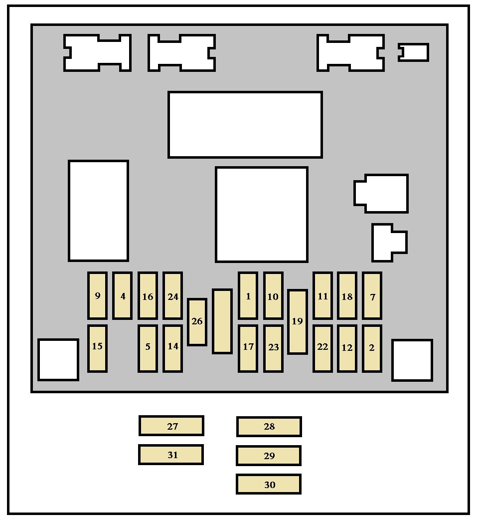
| Pozycja | Amperaż [A] | Chroniony obwód / funkcja |
|---|---|---|
| F1 | 10 | Rear fog lamp |
| F2 | – | Unused socket in the early CC installation |
| F4 | 15 | Front electric windows, deployable rollover hoops and retractable roof control |
| F5 | 15 | Left brake lamp, including trailer braking circuit |
| F7 | 30 | Front/rear courtesy lighting, map-reading lamps, front 12 V socket and glovebox light |
| F9 | 30 | Front window motors and one-touch window operation |
| F10 | 15 | Vehicle diagnostic connection, rear 12 V outlet and trailer electrical feed |
| F11 | 20 | Radio, multifunction display, steering-wheel controls, automatic gearbox and roof-control ECU |
| F12 | 10 | Right side lamps, number-plate and trailer lights, switch lighting, A/C panel and cigarette lighter |
| F14 | 30 | Door locking/unlocking and deadlocking |
| F15 | 30 | Rear one-touch electric windows and hinged roof-cover motors |
| F16 | 10 | Engine fuse board supply, alarm, steering-wheel electronics and airbag ECU |
| F17 | 10 | Right brake lamp and high-mounted third stop light |
| F18 | 10 | Diagnostic port, electrochromic mirror, brake/clutch switches, coolant-level sensing and steering controls |
| F19 | Shunt (30 A slot) | PARC transport/parking shunt in nominal 30 A holder – not a normal fuse |
| F22 | 10 | Left parking/side lights, registration-plate lighting and trailer lights |
| F23 | 15 | Factory alarm siren and passenger-compartment volumetric alarm sensor |
| F24 | 15 | Instrument cluster, radio, display, A/C, rear parking assistance and rain/light sensors |
| F26 | 30 | Electrically heated rear window |
Supplementary F27-F31 – differences between manual editions
On 22 September 2003 F27 is unused and F28 (40 A) supplies the hydraulic roof pump. On 15 December 2003 F27 (20 A) protects heated seats, F28 (40 A) the pump, F29 (10 A) airbags and F30 (10 A) the rollover hoops. On 30 August 2004 F27 and F28 retain their functions, but F30 becomes a 20 A JBL audio feed and F31 (10 A) protects rollover hoops. Using F30 without checking the edition would identify the wrong circuit.
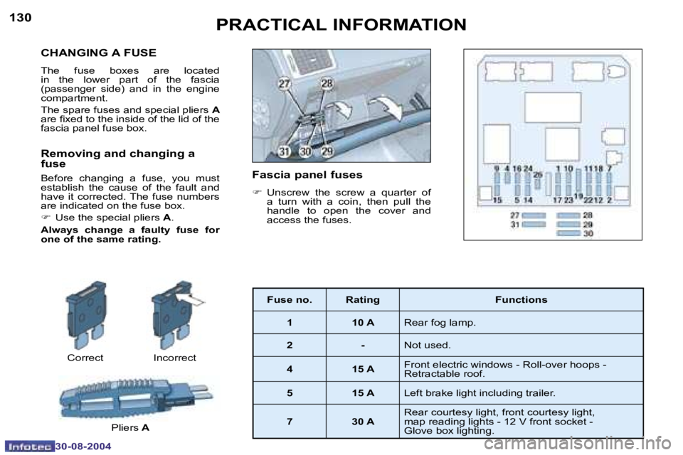
| Pozycja | Amperaż [A] | Chroniony obwód / funkcja |
|---|---|---|
| F27 | – | 22.09.2003: 22 Sep 2003: Unused supplementary fuse position |
| F28 | 40 | 22.09.2003: 22 Sep 2003: Hydraulic retractable-roof pump |
| F27 | 20 | 15.12.2003: 15 Dec 2003: Heated front seats on equipped cars |
| F28 | 40 | 15.12.2003: 15 Dec 2003: Hydraulic retractable-roof pump |
| F29 | 10 | 15.12.2003: 15 Dec 2003: Airbags and SRS controller |
| F30 | 10 | 15.12.2003: 15 Dec 2003: Deployable rollover protection hoops |
| F27 | 20 | 30.08.2004: 30 Aug 2004: Heated front seats |
| F28 | 40 | 30.08.2004: 30 Aug 2004: Hydraulic retractable-roof pump |
| F29 | 10 | 30.08.2004: 30 Aug 2004: Airbags and SRS |
| F30 | 20 | 30.08.2004: 30 Aug 2004: JBL premium audio amplifier |
| F31 | 10 | 30.08.2004: 30 Aug 2004: Deployable rollover protection hoops |
Engine-compartment fuses F1-F18
The engine panel includes fuel pump F2 (15 A), horn F13 (15 A), front wipers F17 (30 A), A/C blower F18 (40 A) and individual headlamp fuses. The 2003-2004 handbook lists F7 as an unused socket despite a nominal 20 A appearing in some tables. Do not fill it by copying a headlamp-washer allocation from another 307 generation. F16 (30 A) powers the secondary-air pump on applicable petrol automatic versions.
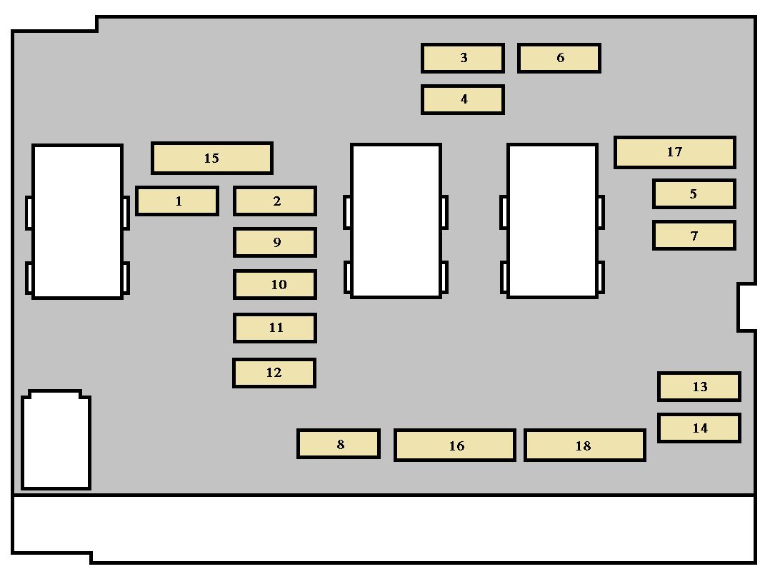
| Pozycja | Amperaż [A] | Chroniony obwód / funkcja |
|---|---|---|
| F1 | 10 | Reversing lamp switching on manual/automatic gearboxes, starter interlock and vehicle speed sensor |
| F2 | 15 | Fuel pump and petrol EVAP purge valve |
| F3 | 10 | Power steering electronics and ABS/ESP controller |
| F4 | 10 | Engine injection ECU, radiator fan relay, auxiliary heater and automatic gearbox shift lock |
| F5 | – | Unused fuse position |
| F6 | 15 | Front fog lamps |
| F7 | 20 | Unused in the original CC 2003-2004 handbook despite nominal 20 A in some listings; not a headlamp washer feed on this version |
| F8 | 20 | Cooling fan relay control and engine ECU power |
| F9 | 15 | Left dipped-beam headlamp |
| F10 | 15 | Right dipped-beam headlamp |
| F11 | 10 | Right main-beam headlamp |
| F12 | 10 | Left main-beam headlamp |
| F13 | 15 | Horn |
| F14 | 10 | Front windscreen washer pump |
| F15 | 30 | Oxygen sensors, EGR valve, ignition coil and engine injection actuators |
| F16 | 30 | Secondary air-injection pump on suitable petrol automatic engines |
| F17 | 30 | Front windscreen wiper motor at both speeds |
| F18 | 40 | Cabin heating and A/C blower motor |
Maxi fuse protection including the retractable roof
MF1 (50 A) powers the radiator fan, MF2 and MF3 (30 A each) protect ABS/ESP, MF4 and MF5 (70 A each) supply the BSI and MF8 (70 A) the electro-hydraulic steering pump. MF6 (60 A) feeds the hardtop hydraulic system and, in some 2004 equipment configurations, heated seats. F28 (40 A) is an additional separate pump fuse. Do not increase the rating to avoid a roof fault.
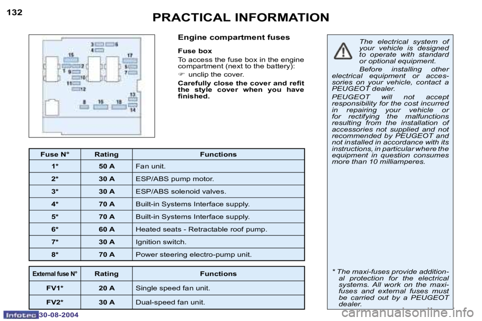
| Pozycja | Amperaż [A] | Chroniony obwód / funkcja |
|---|---|---|
| MF1 | 50 | Engine cooling fan high-current circuit |
| MF2 | 30 | ABS/ESP hydraulic pump motor |
| MF3 | 30 | ABS/ESP valve solenoids |
| MF4 | 70 | First BSI body electronics main supply |
| MF5 | 70 | Second BSI high-current supply |
| MF6 | 60 | Retractable hardtop hydraulic pump high-current feed; 2004 manuals may also include optional heated seats |
| MF7 | 30 | Ignition switch main electrical supply |
| MF8 | 70 | Electro-hydraulic power steering pump |
External fan fuses FV1 and FV2
FV1 (20 A) protects a single-speed cooling fan and FV2 (30 A) a two-speed fan where these external links are fitted. They are not extra standard cabin fuse slots. Use the exact cooling equipment identification before replacing either link.
| Pozycja | Amperaż [A] | Chroniony obwód / funkcja |
|---|---|---|
| FV1 | 20 | External single-speed radiator fan circuit |
| FV2 | 30 | External two-speed radiator fan circuit |
Why will the retractable roof not fold?
Hydraulic motor silent: Check supplementary F28 (40 A) and engine Maxi MF6 (60 A), then the battery, boot locking, luggage-divider switch, roof position sensors and hydraulic equipment. Roof control does not respond: Cabin F11 (20 A) and F4 (15 A) are relevant feeds. Roof flap or rear window stops: Cabin F15 (30 A) supplies the hinged cover motor and rear electric windows. Never bridge the safety interlocks or force a blocked hydraulic mechanism.
Front 12 V socket dead: Cabin F7 (30 A); rear outlet: F10 (15 A). Rear demister: F26 (30 A) and heated-glass connectors. Rollover protection warning: Verify whether the fitted handbook puts the rollover protection at F30 or F31 before attempting SRS diagnosis.
Related Peugeot fuse box guides
The later Peugeot 307 CC (2005) uses a 30 A F40 roof-pump fuse and has two distinct wiring variants. The Peugeot 307 CC (2006-2008) retains the newer roof system. The 307 hatchback and 307 SW estate do not use this folding metal roof hydraulic layout.
Technical sources: Peugeot 307 CC manufacturer’s owner’s handbooks dated 22 September 2003, 15 December 2003 and 30 August 2004. Factory equipment and VIN-specific production variant determine the fitted fuse allocation.