
The Peugeot 307 CC underwent an important electrical revision in 2005. Early cars use different dashboard and engine fuse allocations from the facelift specification covered by the 1 October 2005 Peugeot handbook. The changes affect the rear 12 V socket, parking assistance and headlamp washing, but both versions use F40 at 30 A for the hydraulic retractable-roof pump. All original positions are preserved in six tables. One additional early-2005 F39 20 A heated-seat fuse has been restored using the official 1 March 2005 Peugeot 307 CC handbook, which lists it even though the original Polish article omitted it.
Where are the Peugeot 307 CC fuse boxes?
Passenger compartment: Turn the ignition off and open the lower dashboard fuse hatch. In left-hand-drive cars it is normally accessible from the driver-side fascia; right-hand-drive Peugeot handbooks may describe passenger-side or glovebox access. Rotate the catch a quarter-turn with a coin and lower the flap to reach the blade fuses. The puller and spares are mounted inside the cover. F36, F39 and F40 are additional body-equipment circuits; they do not share the numbering of the ordinary engine panel.
Engine bay: Lift the bonnet and find the covered distribution unit next to the battery. Unclip the lid and inspect F1-F18. Larger Maxi links protect the BSI, ABS, fan and steering systems and require professional handling. Secure the lid against moisture after inspection.
How to distinguish early and late 2005 wiring
The most useful clue is the rear 12 V socket: early 2005 protects it with cabin F8 20 A while F9 30 A supplies the front lighter. After the update, F9 30 A supplies both front and rear outlets. Cabin F12 changes from unused to 15 A for rear parking assistance and optional audio controls. Under the bonnet, early F4 is unused, whereas post-facelift F4 at 20 A feeds headlamp washers on equipped vehicles. These distinctions should be checked against the fitted fuse board, not assumed from first registration date alone.
Common 307 CC fuse locations
The roof pump uses F40 30 A in both 2005 layouts. Engine F2 for the horn and engine F12 for the windscreen wipers are not the same positions as cabin F2 locking and cabin F12 parking equipment.
| Pozycja | Amperaż [A] | Chroniony obwód / funkcja |
|---|---|---|
| F9 | 30 | Front 12 V outlet in both early and late 2005 CC configurations |
| F8/F9 | 20 / 30 | Rear 12 V outlet: F8 20 A in early 2005, F9 30 A after the electrical update |
| F40 | 30 | Hydraulic retractable-roof pump, extra dashboard fuse |
| F36 | 20 | Hi-Fi amplifier, extra dashboard fuse |
| F17 | 40 | Electrically heated rear window |
| F2 | 15 | Horn in ENGINE compartment, not cabin F2 |
| F5 | 15 | Fuel pump in ENGINE compartment |
| F12 | 30 | Front wiper motor in ENGINE compartment, not cabin F12 |
Passenger-compartment fuse box – early 2005
The early CC panel has unused F1, F2 30 A for deadlocking, F3 5 A for airbags, F8 20 A for audio, alarm and the rear socket, and F9 30 A for the front outlet. F12 is unused and F16 a special PARC configuration shunt. F17 40 A protects the heated rear window. Supplementary F36 20 A powers Hi-Fi, F40 30 A powers the retractable roof pump, and F39 20 A for factory heated seats is confirmed in the manufacturer’s March 2005 manual and included here.
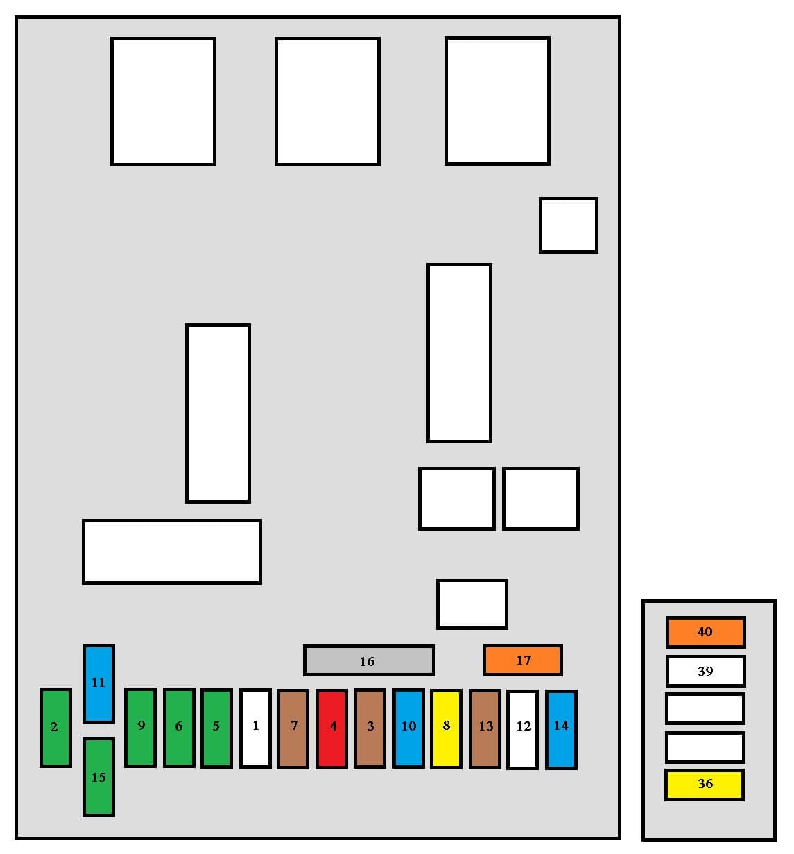
| Pozycja | Amperaż [A] | Chroniony obwód / funkcja |
|---|---|---|
| F1 | – | Unused fuse socket |
| F2 | 30 | Central locking and deadlocking |
| F3 | 5 | Airbags and pyrotechnic belt-pretensioner ECU |
| F4 | 10 | STOP brake/clutch switches, coolant-level sensor, steering-angle sensor, ESP, diagnostic socket and auto-dimming mirror |
| F5 | 30 | Front electric windows and heated exterior mirrors |
| F6 | 30 | Rear electric windows and retractable-roof articulated cover actuators |
| F7 | 5 | Front and rear courtesy lamps, reading lamps and glovebox illumination |
| F8 | 20 | Radio/telephone, multifunction display, alarm, trailer interface and rear 12 V socket on the early layout |
| F9 | 30 | Front 12 V outlet (both front and rear outlets on the later layout) |
| F10 | 15 | Automatic transmission ECU, brake STOP switch and optional under-inflation warning |
| F11 | 15 | Diagnostic port, low-current ignition/anti-theft supply and HDi particulate-filter ECU on later equipment |
| F12 | – | Unused in the early-2005 layout; later rear parking sensors and optional Hi-Fi electrical control |
| F13 | 5 | Engine fuse board and rain/light sensor power |
| F14 | 15 | Trailer module, instruments, automatic A/C, airbags and pyrotechnic belt pretensioners |
| F15 | 30 | Main locking and deadlocking electrical supply |
| F16 | Shunt | PARC parking/transport-mode configuration shunt, not a conventional fuse |
| F17 | 40 | Heated rear-window demister |
| F36 | 20 | Hi-Fi sound amplifier on equipped cars |
| F39 | 20 | Optional heated driver and passenger front seats – confirmed in Peugeot 307 CC owner’s handbook dated 1 March 2005; this position was missing from the Polish early-2005 table |
| F40 | 30 | Hydraulic retractable hardtop roof pump |
Passenger-compartment fuse box – post-facelift 2005
After the update F9 30 A supplies both 12 V outlets and F8 no longer includes the rear one. F10 15 A now also covers tyre-pressure electronics where equipped; F12 15 A serves rear parking assistance and optional Hi-Fi electronics. F14 can include rollover protection, while F36 20 A remains the Hi-Fi amplifier feed, F39 20 A optional heated front seats and F40 30 A the roof-pump circuit. Do not substitute another fuse size because the connector looks the same.
| Pozycja | Amperaż [A] | Chroniony obwód / funkcja |
|---|---|---|
| F1 | – | Unused fuse socket |
| F2 | 30 | Central locking and deadlocking |
| F3 | 5 | Airbags and pyrotechnic belt-pretensioner ECU |
| F4 | 10 | STOP brake/clutch switches, coolant-level sensor, steering-angle sensor, ESP, diagnostic socket and auto-dimming mirror; diesel particle-filter additive pump on equipped cars |
| F5 | 30 | Front electric windows and heated exterior mirrors |
| F6 | 30 | Rear electric windows and retractable-roof articulated cover actuators |
| F7 | 5 | Front and rear courtesy lamps, reading lamps and glovebox illumination |
| F8 | 20 | Radio/telephone, display, factory alarm, trailer controls and steering-wheel switches; rear 12 V supply moved to F9 |
| F9 | 30 | Front and rear 12 V accessory sockets, 30 A |
| F10 | 15 | Automatic transmission ECU, brake STOP switch and optional under-inflation warning |
| F11 | 15 | Diagnostic port, low-current ignition/anti-theft supply and HDi particulate-filter ECU on later equipment |
| F12 | 15 | Rear parking assistance and related Hi-Fi control equipment, where fitted |
| F13 | 5 | Engine fuse board and rain/light sensor power |
| F14 | 15 | Trailer service module, instrument cluster, automatic A/C, airbags and belt pretensioners, later rollover hoop control and hands-free system |
| F15 | 30 | Main locking and deadlocking electrical supply |
| F16 | Shunt | PARC parking/transport-mode configuration shunt, not a conventional fuse |
| F17 | 40 | Heated rear-window demister |
| F36 | 20 | Hi-Fi sound amplifier on equipped cars |
| F39 | 20 | Factory optional heated driver and passenger seats |
| F40 | 30 | Hydraulic retractable hardtop roof pump |
Early-2005 engine compartment F1-F18
Engine F2 15 A protects the horn, F5 15 A the fuel pump, F11 40 A the heating/A/C blower and F12 30 A the front wipers. F4 is unused in this edition, while F8 at 20 A is described as an ignition-feed circuit. The physical original engine fuse diagram is reproduced below; later production uses some different functions.
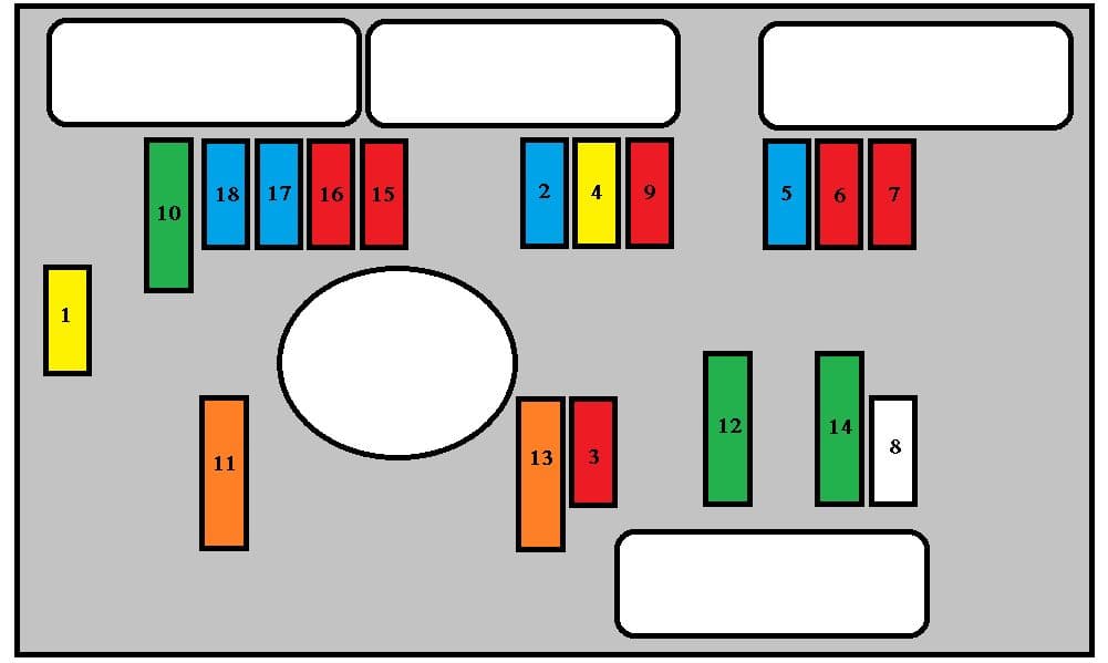
| Pozycja | Amperaż [A] | Chroniony obwód / funkcja |
|---|---|---|
| F1 | 20 | Engine ECU and high-speed cooling-fan relays |
| F2 | 15 | Horn |
| F3 | 10 | Front windscreen washer pump |
| F4 | – | Unused in early 2005; after the update, headlamp washer pump rated 20 A |
| F5 | 15 | Fuel pump and petrol evaporative-emissions purge valve |
| F6 | 10 | Four-speed automatic transmission controller, shift interlock, radiator fan relay and Xenon headlamp control as equipped |
| F7 | 10 | ABS/ESP ECU and electric power-steering control |
| F8 | 20 | Early ignition circuit; after the update starter motor solenoid control |
| F9 | 10 | Additional diesel engine heater and coolant-level sensing |
| F10 | 30 | Engine management actuators, coils, fuel injectors, oxygen sensors and solenoid valves |
| F11 | 40 | Heater/air-conditioning blower motor |
| F12 | 30 | Front wiper motor in low and high speed |
| F13 | 40 | BSI supply after ignition switch |
| F14 | 30 | Secondary air pump on applicable 2.0-litre petrol engines |
| F15 | 10 | Right main-beam headlamp |
| F16 | 10 | Left main-beam headlamp |
| F17 | 15 | Left dipped-beam headlamp |
| F18 | 15 | Right dipped-beam headlamp |
Engine compartment after the 2005 update
On the later installation F4 20 A operates headlamp washers when fitted and F8 20 A is specifically the starter solenoid control. F2 remains a 15 A horn circuit, F12 a 30 A wiper feed and F11 a 40 A blower feed. F15-F18 separately protect the right and left main/dipped beams. Automatic gearbox, petrol/diesel engine and Xenon options change other consumers.
| Pozycja | Amperaż [A] | Chroniony obwód / funkcja |
|---|---|---|
| F1 | 20 | Engine ECU and high-speed cooling-fan relays |
| F2 | 15 | Horn |
| F3 | 10 | Front windscreen washer pump |
| F4 | 20 | Headlamp washer pump, 20 A in the post-facelift configuration |
| F5 | 15 | Fuel pump and petrol evaporative-emissions purge valve |
| F6 | 10 | Four-speed automatic transmission controller, shift interlock, radiator fan relay and Xenon headlamp control as equipped |
| F7 | 10 | ABS/ESP ECU and electric power-steering control |
| F8 | 20 | Starter solenoid control after the 2005 electrical update |
| F9 | 10 | Additional diesel engine heater and coolant-level sensing |
| F10 | 30 | Engine management actuators, coils, fuel injectors, oxygen sensors and solenoid valves |
| F11 | 40 | Heater/air-conditioning blower motor |
| F12 | 30 | Front wiper motor in low and high speed |
| F13 | 40 | BSI supply after ignition switch |
| F14 | 30 | Secondary air pump on applicable 2.0-litre petrol engines |
| F15 | 10 | Right main-beam headlamp |
| F16 | 10 | Left main-beam headlamp |
| F17 | 15 | Left dipped-beam headlamp |
| F18 | 15 | Right dipped-beam headlamp |
High-current Maxi fuse protection
The source documents the post-facelift MF series: MF1 30 or 50 A according to cooling fan wattage, MF2 and MF3 30 A each for ABS/ESP, MF4 and MF5 80 A each for BSI power, MF6 80 A for the cabin distribution carrier and MF8 70 A for power steering. An MF7 or a complete pre-facelift Maxi allocation is not documented in the Polish source, so those missing ratings are not guessed. Do not apply these later sizes to an early-2005 high-current box.
| Pozycja | Amperaż [A] | Chroniony obwód / funkcja |
|---|---|---|
| MF1 | 30 / 50 | Radiator cooling fan motor, 30 A with 200 W fan or 50 A with 400-460 W fan |
| MF2 | 30 | ABS/ESP hydraulic pump |
| MF3 | 30 | ABS/ESP solenoid valves |
| MF4 | 80 | First high-current 80 A BSI main power feed |
| MF5 | 80 | Second high-current 80 A BSI main power feed |
| MF6 | 80 | Passenger-compartment fuse carrier high-current supply |
| MF8 | 70 | Electric power-steering pump main supply |
Why will the folding roof not move?
Hydraulic pump is silent: Check the 2005 CC’s supplementary F40 30 A, then battery voltage, the boot luggage divider, boot latch, four windows, folding cover position and roof microswitches. Never bridge roof safety interlocks or force the mechanism to overcome a fault. Hinged roof covers do not open: Cabin F6 30 A feeds the rear windows and cover motor. Front power windows fail: Cabin F5 30 A, switches and door wiring.
Rear 12 V socket dead: Check early F8 20 A or later F9 30 A; if the front outlet works, inspect the rear socket connections. Hi-Fi system silent: F36 20 A and, after the update, the optional F12 15 A associated control. Heated seats: F39 20 A on equipped cars. Rear demister: F17 40 A. Parking sensors: After the update cabin F12 15 A and the rear sensor loom.
Earlier and later Peugeot 307 CC versions
The Peugeot 307 CC 2003-2004 used an earlier F28 40 A roof fuse and a 60 A Maxi MF6, not the later F40 arrangement. The 307 CC 2006-2008 follows the newer electrical layout. The 307 SW estate has a panoramic roof blind but no CC hydraulic retractable hardtop pump.
Technical basis: Peugeot 307 CC manufacturer’s 1 March 2005 handbook and the post-update 1 October 2005 fuse charts. Verify exact engine, production date, market and optional equipment using the original cover and documentation.