
Peugeot 407 vehicles built in 2006 were supplied with more than one electrical distribution layout. The fuse tables in this guide separate variant A, with a dashboard F10 20 A power outlet and G36-G40 equipment group, from variant B, which uses dashboard F9 30 A for the cigarette lighter/rear 12 V supply and G29-G40. These are distinct installations, not two diagrams for simultaneous use on one car. All 82 original fuse and shunt positions across seven tables are preserved, including unused positions and the optional luggage-compartment box.
Peugeot 407 fuse box locations and access
Inside the cabin: Turn off the ignition, open the lower dashboard service compartment on the driver side of a European left-hand-drive car and release its top retaining tabs. The fuse carrier can be lowered for access. Some right-hand-drive owner’s manuals instead direct the driver through the glovebox on the passenger side. The puller may be fitted beside the panel. Use the fitted cover legend to distinguish variants before removing any fuse.
Under the bonnet: With the ignition off, lift the bonnet and locate the covered electrical box alongside the battery. Remove the battery trim if it blocks the lid, release the fuse-box retaining clips and lift the cover. Reseat the cover securely after inspection to prevent moisture entering the terminals. High-current F10-F14 protection may need the manufacturer’s specific service procedure.
In the luggage compartment: On equipped variants a separate F1-F5 panel is behind a side trim service flap, normally on the left in the source European arrangement. Open the boot or tailgate, loosen the service-cover fasteners and inspect the carrier. Not every trim version has the same optional rear electrical group.
Identifying variant A and variant B
If the cabin carrier has F1, F4-F7, F9-F12, F14-F16 and the separate F20-F22 positions, it corresponds to variant A. In this layout F10 at 20 A protects the front lighter and power socket, and F16 at 30 A protects central locking. Variant B has F1-F15, an F17 rear-demister position and G29-G40 supplementary sockets; F9 at 30 A is the lighter and rear outlet circuit. Compare the physical diagrams and the installed fuse labels rather than selecting a version from the registration year alone.
Variant A – passenger-compartment fuses and FS1
The diagram below is a higher-resolution match for the A-type cabin fuse positions. It replaces the small 300-pixel illustration in the Polish source while preserving the layout. FS1 is the special PARC transport/parking shunt. Positions F7 and F20-F22 can be unused even where the handbook lists a nominal current rating.
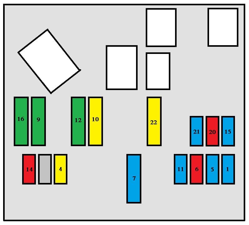
| Pozycja | Amperaż [A] | Chroniony obwód / funkcja |
|---|---|---|
| F1 | 15 | OBD diagnostic connector and low-current steering-column anti-theft protection |
| F4 | 20 | Boot and trailer service box, steering-wheel controls, radio, alarm, navigation/telematics, multifunction display and automatic gearbox where installed |
| F5 | 15 | Alarm siren and tyre-pressure monitoring |
| F6 | 10 | Automatic gearbox, clutch switch, electrochromic mirror, reading lights, OBD connection, ESP and steering-angle sensing, SW panoramic roof blind and Saloon sunroof |
| F7 | 15 | Not occupied in the 2006 layout A despite its printed nominal rating |
| F9 | 30 | Rear one-touch electric windows |
| F10 | 20 | Front cigarette lighter and 12 V accessory socket (100 W maximum), glovebox light and telematics on relevant markets |
| F11 | 15 | Electronic rear child lock and door deadlocking |
| F12 | 30 | Front one-touch electric windows |
| F14 | 10 | Engine and boot fuse distribution, trailer service module, wiper relay and electric-seat memory |
| F15 | 15 | Instrument cluster, climate controller, rain/light sensors, electric seats, airbags and hands-free telephone |
| F16 | 30 | Door central locking and deadlocking |
| F20 | 10 | Unused fuse position on this factory panel |
| F21 | 15 | Unused fuse position on this factory panel |
| F22 | 20 | Unused fuse position on this factory panel |
| FS1 | Shunt | FS1 PARC parking / transport-mode configuration shunt, not a replaceable fuse |
Variant A – supplementary fuses G36-G40
These sockets feed equipment such as a six-speed automatic gearbox, heated seats and electric seat adjustment or memory. A lack of a fitted accessory may mean the corresponding socket is unoccupied; this five-position group is not the same as the G29-G40 panel of variant B.
| Pozycja | Amperaż [A] | Chroniony obwód / funkcja |
|---|---|---|
| G36 | 30 | Electric right-hand seat or Hi-Fi amplifier depending on the installed equipment |
| G37 | 15 | Six-speed automatic transmission control power |
| G38 | 30 | Driver and passenger heated front seats |
| G39 | 30 | Electric-seat position memory module |
| G40 | 30 | Electric left-hand seat adjustment |
Variant A – engine-compartment fuses 1-14
The original engine diagram is kept with its table. It covers the horn, wash-wipe pumps, headlamp washers, fuel pump, power steering, starter solenoid and engine management. Fuse 8 at 20 A supplies the starter solenoid control coil; it is not an ignition coil.
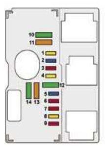
| Pozycja | Amperaż [A] | Chroniony obwód / funkcja |
|---|---|---|
| 1 | 20 | Engine management ECU |
| 2 | 15 | Horn |
| 3 | 10 | Front screen washer pump and SW rear-screen wash supply where fitted |
| 4 | 20 | Headlamp washer pump |
| 5 | 15 | Fuel pump on compatible engines |
| 6 | 10 | Automatic gearbox ECU |
| 7 | 10 | Power steering control unit |
| 8 | 20 | Starter solenoid coil, not an ignition coil |
| 9 | 10 | Xenon headlamp electronics, brake-pedal switch and halogen headlamp levelling |
| 10 | 30 | Engine management actuators, ignition coils, solenoid valves and lambda sensors |
| 11 | 40 | Climate-control blower motor, or unoccupied on certain versions |
| 12 | 30 | Front windscreen wiper motor |
| 13 | 40 | BSI body electronics feed after switching on ignition |
| 14 | 30 | Secondary air-injection pump when fitted |
Variant A – separate luggage-compartment fuse box
The rear F1-F5 group is installed on equipped variants and protects the SW rear wiper, fuel filler flap latch, rear 12 V socket, diesel particulate-filter equipment and rear window heating. Rear fuse F3 at 15 A is not the same physical position as the engine or cabin F3.
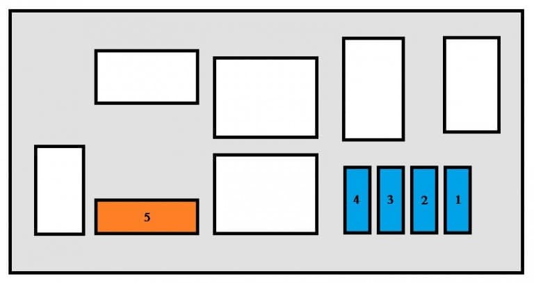
| Pozycja | Amperaż [A] | Chroniony obwód / funkcja |
|---|---|---|
| F1 | 15 | Rear window wiper on vehicles equipped with it, particularly SW estate |
| F2 | 15 | Fuel-filler flap locking actuator |
| F3 | 15 | Rear luggage compartment 12 V power socket |
| F4 | 15 | Diesel particulate filter (FAP) control supply |
| F5 | 40 | Heated rear window / demister |
Variant B – later-style dashboard fuse carrier
Variant B has substantially different fuse positions and circuit assignments. For example, cabin F2 at 30 A covers central locking, F9 at 30 A covers the lighter and rear accessory socket, and F17 at 40 A protects the heated rear screen. The original schematic is retained rather than substituting a visually similar earlier BSI carrier.

| Pozycja | Amperaż [A] | Chroniony obwód / funkcja |
|---|---|---|
| F1 | 15 | Rear windscreen wiper on 407 SW |
| F2 | 30 | Central locking and deadlocking |
| F3 | 5 | Supplementary restraint system (SRS) airbags |
| F4 | 10 | ESP control sensor, diagnostic socket, Saloon sunroof and steering-wheel angle sensor |
| F5 | 30 | Front sequential electric windows and the Saloon sunroof or SW panoramic roof blind |
| F6 | 30 | Rear electric windows |
| F7 | 5 | Glovebox and interior reading lamps, side repeaters and courtesy mirror lighting |
| F8 | 20 | Radio and CD changer, multifunction display, steering controls, alarm, trailer module and telematics/navigation |
| F9 | 30 | 12 V lighter and rear accessory power socket (100 W maximum), plus telematics depending on market |
| F10 | 15 | Tyre-pressure monitoring ECU |
| F11 | 15 | Electronic rear child lock and door deadlocking |
| F12 | 30 | Hands-free kit, trailer and rear parking aid equipment, electric passenger seat, rain/light sensor and alarm |
| F13 | 5 | Engine-compartment fuse box and front-wiper relay control |
| F14 | 15 | Driver seat memory, instruments, climate panel and airbag electronics |
| F17 | 40 | Rear window demister |
| FS1 | Shunt | FS1 PARC parking-mode shunt, not a conventional fuse |
Variant B – supplementary fuses G29-G40
The longer G-series carrier includes telematics, power seats, rear accessory sockets, seat heating, automatic gearbox supply and audio amplification. G33-G35 are explicitly unused. G39 is shown as an optional trailer module without a manufacturer-specified amperage in this source, so no value has been invented.
| Pozycja | Amperaż [A] | Chroniony obwód / funkcja |
|---|---|---|
| G29 | 5 | Telematics supply, where factory installed |
| G30 | 30 | Electric driver’s seat without memory control |
| G31 | 30 | Electric passenger seat without memory control |
| G32 | 15 | Rear 12 V accessory socket, nominal maximum load 100 W |
| G33 | – | Unused location |
| G34 | – | Unused location |
| G35 | – | Unused location |
| G36 | 30 | Driver seat memory controller |
| G37 | 15 | Six-speed automatic gearbox power supply |
| G38 | 30 | Driver and passenger heated front seats |
| G39 | – | Trailer service module on equipped vehicles; no amperage specified in the reference |
| G40 | 30 | Hi-Fi amplifier / audio system |
Variant B – under-bonnet fuse box 1-14
The B engine panel has the same basic 14 numbered positions but differs from A in its description of F5, F7 and F9, which can include fuel vapour controls, additional stop/clutch switches, an electric power steering pump or the 407 SW panoramic blind. Check the actual engine and equipment before diagnosing a supply failure.

| Pozycja | Amperaż [A] | Chroniony obwód / funkcja |
|---|---|---|
| 1 | 20 | Engine ECU |
| 2 | 15 | Horn |
| 3 | 10 | Front washer and optional SW rear washer |
| 4 | 20 | Headlamp washing circuit |
| 5 | 15 | Engine-management peripherals, petrol fuel pump and EVAP purge valve where fitted |
| 6 | 10 | Automatic transmission ECU |
| 7 | 10 | Protection and switching module, air flow meter, clutch/stop switches, auto-dimming mirror, automatic gearbox and SW panoramic roof blind controls |
| 8 | 20 | Starter solenoid control coil |
| 9 | 10 | Xenon lighting electronics, stop-light switch, electric power steering pump and automatic gearbox electronics where fitted |
| 10 | 30 | Engine control actuators, ignition coils, solenoids and oxygen sensors |
| 11 | 40 | Heater and air-conditioning blower, or unoccupied depending on engine and trim |
| 12 | 30 | Front windscreen wiper drive |
| 13 | 40 | BSI feed following ignition-on |
| 14 | 30 | Secondary air-injection pump where factory fitted |
Common problems – which 407 fuse should you check?
Front 12 V socket or lighter is dead: In A, inspect cabin F10 (20 A); in B, inspect cabin F9 (30 A). Check the socket for metal debris before installing a fuse. No radio or display: A uses F4 (20 A), B includes F8 (20 A). Central locking fails: A uses F16 (30 A), B F2 (30 A). Damaged door loom wiring can affect only one door.
Windscreen wipers fail: Engine fuse 12 (30 A) protects the drive, while the cabin control supply depends on variant. Horn not sounding: Engine fuse 2 (15 A). Starter does not crank: Engine fuse 8 (20 A) relates to the solenoid, followed by battery, grounds and starter relay tests. No heated rear window: Variant A can use luggage F5 (40 A), whereas B has cabin F17 (40 A).
Fuse box diagrams for adjacent Peugeot 407 years
The Peugeot 407 (2004) uses the initial production fuse allocation. For later Saloon/SW electrical equipment, see Peugeot 407 (2007-2011), which also documents separate Coupe differences. Avoid transferring fuse ratings between body and production-year layouts without checking the panel.
Technical references: Peugeot 407 2006 owner-handbook and wiring allocations, including two passenger fuse-panel configurations, original engine and luggage panels, and supplementary equipment circuits. Equipment, driving side and market affect the physical installation.