
The Peugeot 307 Break (2005-2008), called the 307 Kombi in Poland, is the conventional estate version, distinct from the SW with its panoramic-roof shade. Its fuse allocation also changed after 2005. This guide preserves all 87 entries from the original article, including eight quick-reference rows, separate early and late dashboard and engine tables, unoccupied slots, a PARC mode shunt and Maxi power links.
Where are the Peugeot 307 Break fuses?
Dashboard: With ignition off, open the small service flap at the lower driver’s side of a left-hand-drive 307, release the catch and lower the panel. The fuse puller and spare fuses are typically secured inside the cover. On a right-hand-drive car access may be through the passenger glovebox, as directed in its own handbook.
Engine compartment: The protected box is beside the battery. Unclip its lid and compare the fuse positions to the physical panel before removing a fuse. Two engine box layouts exist, and F15-F18 in the source refer to type 1 only. The larger Maxi fuses protect BSI, ABS, fan and electric steering circuits and are not ordinary low-current blades.
Electrical changes after 2005
In the 2005 Break, rear 12 V socket F8 is 20 A and the front lighter is F9 at 30 A. Later both use F9 at 30 A. The engine starter-control F8 changes from 20 A to 25 A in the later manual, which also adds the optional 15 A F41 six-speed automatic gearbox protection. Match the real vehicle before substituting parts, even where the physical board looks identical.
Frequently checked fuses
This eight-row index repeats the positions explained in full tables. Engine F2 for the horn is not the same circuit as cabin F2 for locking.
| Pozycja | Amperaż [A] | Chroniony obwód / funkcja |
|---|---|---|
| F9 | 30 | 2005 and 2007-2008 – front 12 V lighter socket in cabin |
| F8 | 20 | 2005 rear socket F8 (20 A); later rear socket moves to cabin F9 (30 A) |
| F2 | 15 | Horn in the ENGINE compartment, not cabin F2 |
| F12 | 30 | Front windscreen wipers in ENGINE compartment, not cabin F12 |
| F17 | 40 | Heated rear window in cabin |
| F39 | 20 | Front heated seats in later models if equipped; earlier rating depends on equipment |
| F8 | 20 / 25 | Starter control in ENGINE compartment: 20 A in 2005 or 25 A later |
| F41 | 15 | Six-speed automatic gearbox ECU in later engine carrier, not listed for 2005 |
Passenger-compartment fuse box – 2005 Break
Cabin F1 (15 A) protects the rear wiper, F2 and F15 (30 A) the locking circuits, F8 (20 A) the rear outlet and F9 (30 A) the front power socket. The 2005 Break F12 (15 A) is allocated to driving-school equipment. F16 is a PARC configuration shunt, not a substitute for an amperage-rated fuse.
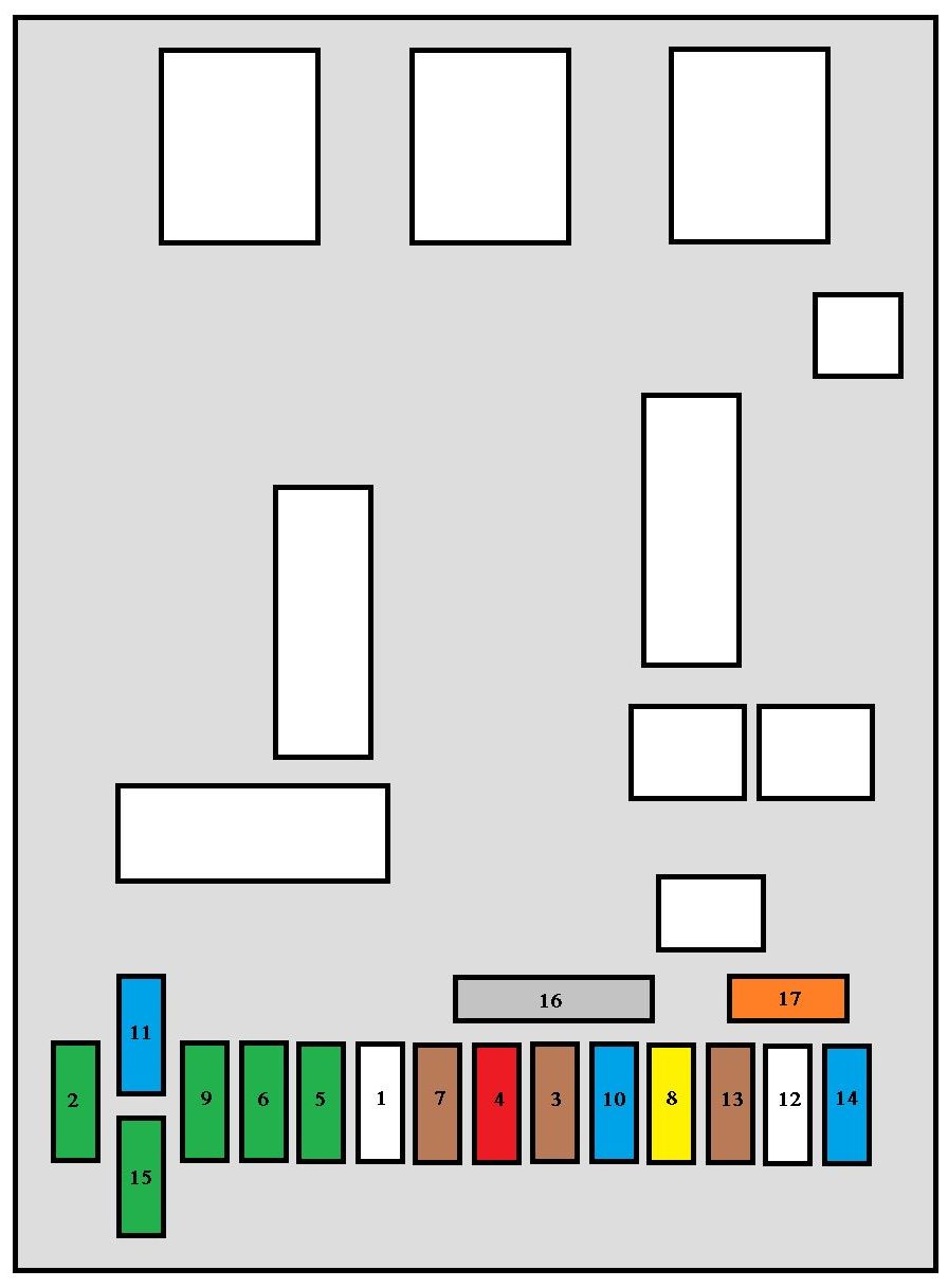
| Pozycja | Amperaż [A] | Chroniony obwód / funkcja |
|---|---|---|
| F1 | 15 | Tailgate rear windscreen wiper motor |
| F2 | 30 | Central door locking and deadlocking |
| F3 | 5 | Airbag ECU and pyrotechnic seat-belt pretensioners |
| F4 | 10 | Brake/STOP and clutch switches, engine coolant-level sensor, steering angle and ESP, FAP additive pump, diagnostic connector and electrochromatic mirror |
| F5 | 30 | Front electric windows, sunroof where fitted and heated mirrors |
| F6 | 30 | Rear electrically operated windows |
| F7 | 5 | Front and rear courtesy lamps, map lights and glovebox illumination |
| F8 | 20 | Audio, telephone, display, alarm, rear 12 V socket, trailer module and steering-wheel controls |
| F9 | 30 | Front 12 V lighter / accessory socket (rear socket is separately supplied) |
| F10 | 15 | Automatic transmission controller, tyre-pressure warning and STOP switch |
| F11 | 15 | Diagnostic connector, low-current ignition feed and particulate-filter control |
| F12 | 15 | Driving-school electrical module, where installed |
| F13 | 5 | Engine electrical carrier power feed, rain and light sensor |
| F14 | 15 | Trailer module, instrument cluster, automatic A/C, SRS unit, pretensioners and optional hands-free kit |
| F15 | 30 | Central locking and deadlocking main supply |
| F16 | Shunt | PARC parking / transport configuration shunt; not an ordinary fuse |
| F17 | 40 | Heated rear window, NOT the front windscreen |
Passenger-compartment fuse box – 2007-2008 Break
F9 now protects both front and rear 12 V outlets, F8 becomes an audio/alarm and equipment-control circuit, F12 (15 A) adds rear parking assistance and F39 (20 A) is a heated-seat supply when equipped. F17 (40 A) is the rear-window heater, not front screen heating.
| Pozycja | Amperaż [A] | Chroniony obwód / funkcja |
|---|---|---|
| F1 | 15 | Tailgate rear windscreen wiper motor |
| F2 | 30 | Central door locking and deadlocking |
| F3 | 5 | Airbag ECU and pyrotechnic seat-belt pretensioners |
| F4 | 10 | Brake/STOP and clutch switches, engine coolant-level sensor, steering angle and ESP, FAP additive pump, diagnostic connector and electrochromatic mirror |
| F5 | 30 | Front electric windows, sunroof where fitted and heated mirrors |
| F6 | 30 | Rear electrically operated windows |
| F7 | 5 | Front and rear courtesy lamps, map lights and glovebox illumination |
| F8 | 20 | Radio, telephone, display, alarm, trailer control, driving-school module and steering-wheel controls |
| F9 | 30 | Front AND rear 12 V accessory outlets, after the fuse allocation revision |
| F10 | 15 | Automatic gearbox, tyre-pressure monitoring and STOP switch |
| F11 | 15 | Diagnostic connector, low-current ignition feed and particulate-filter control |
| F12 | 15 | Driving-school electrical module and rear parking aid |
| F13 | 5 | Engine electrical carrier power feed, rain and light sensor |
| F14 | 15 | Trailer module, instrument cluster, automatic A/C, SRS unit, pretensioners and optional hands-free kit |
| F15 | 30 | Central locking and deadlocking main supply |
| F16 | Shunt | PARC parking / transport configuration shunt; not an ordinary fuse |
| F17 | 40 | Heated rear window, NOT the front windscreen |
| F39 | 20 | Heated front seats when factory installed |
Engine-compartment fuse panel – 2005 Break
Engine F2 at 15 A serves the horn, F12 at 30 A the front wipers and F11 at 40 A the climate blower. Starter/ignition F8 is 20 A. The manufacturer marks F15-F18 with asterisks because the four individual headlamp fuses apply only to the corresponding type 1 engine carrier.
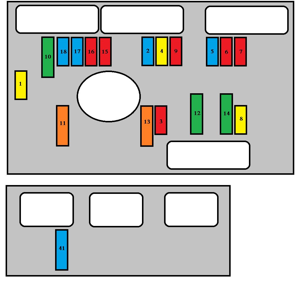
| Pozycja | Amperaż [A] | Chroniony obwód / funkcja |
|---|---|---|
| F1 | 20 | Engine control ECU and radiator cooling fan high-speed relays |
| F2 | 15 | Horn |
| F3 | 10 | Front and rear washer pumps |
| F4 | 20 | Headlamp washer pump, where fitted |
| F5 | 15 | Fuel pump and evaporative canister purge solenoid, depending on engine |
| F6 | 10 | Four-speed automatic gearbox ECU, selector lock, control switch, fan relay and optional Xenon equipment |
| F7 | 10 | ABS/ESP ECU and electric power-steering pump controller |
| F8 | 20 | Ignition switch and starter solenoid control at the 2005 factory rating |
| F9 | 10 | Additional diesel heating, coolant-level warning switch |
| F10 | 30 | Engine management actuators, ignition coils, solenoids, oxygen sensors, injectors and petrol/diesel fuel equipment |
| F11 | 40 | Heater and air-conditioning blower motor |
| F12 | 30 | Front windscreen wiper motor, low and high speeds |
| F13 | 40 | BSI body systems interface supply after ignition |
| F14 | 30 | Secondary air pump on certain 2.0-litre petrol engines |
| F15* | 10 | Right main-beam headlamp |
| F16* | 10 | Left main-beam headlamp |
| F17* | 15 | Left dipped-beam headlamp |
| F18* | 15 | Right dipped-beam headlamp |
Engine compartment – later Break 2007-2008
The later F8 is 25 A for starter control, not the early 20 A. Position F41 (15 A) supplies the six-speed automatic gearbox controller on equipped vehicles. The standard 30 A windscreen wiper and 40 A A/C blower feeds remain in their listed positions.
| Pozycja | Amperaż [A] | Chroniony obwód / funkcja |
|---|---|---|
| F1 | 20 | Engine control ECU and radiator cooling fan high-speed relays |
| F2 | 15 | Horn |
| F3 | 10 | Front and rear washer pumps |
| F4 | 20 | Headlamp washer pump, where fitted |
| F5 | 15 | Fuel pump and evaporative canister purge solenoid, depending on engine |
| F6 | 10 | Four-speed automatic gearbox ECU, selector lock, control switch, fan relay and optional Xenon equipment |
| F7 | 10 | ABS/ESP ECU and electric power-steering pump controller |
| F8 | 25 | Starter solenoid control: 20 A in October 2005, or 25 A in the later 2007.5 handbook |
| F9 | 10 | Additional diesel heating, coolant-level warning switch |
| F10 | 30 | Engine management actuators, ignition coils, solenoids, oxygen sensors, injectors and petrol/diesel fuel equipment |
| F11 | 40 | Heater and air-conditioning blower motor |
| F12 | 30 | Front windscreen wiper motor, low and high speeds |
| F13 | 40 | BSI body systems interface supply after ignition |
| F14 | 30 | Secondary air pump on certain 2.0-litre petrol engines |
| F15* | 10 | Right main-beam headlamp |
| F16* | 10 | Left main-beam headlamp |
| F17* | 15 | Left dipped-beam headlamp |
| F18* | 15 | Right dipped-beam headlamp |
| F41 | 15 | Six-speed automatic gearbox electronic control unit |
High-current MF1-MF8 links
Peugeot Break documentation for 2005 and 2007 specifies MF3 at 30 A and MF4, MF5 and MF6 at 80 A each. The earlier 307 SW may have different ratings. MF1 varies between 30 A and 50 A with radiator fan power; MF2 protects the ABS pump and MF8 at 70 A protects the electric steering pump. Do not add an unlisted MF7 from another car.
| Pozycja | Amperaż [A] | Chroniony obwód / funkcja |
|---|---|---|
| MF1 | 30 / 50 | Radiator cooling fan, 30 A for a 200 W assembly or 50 A for a 400-460 W assembly |
| MF2 | 30 | ABS/ESP hydraulic pump |
| MF3 | 30 | ABS/ESP solenoid valves |
| MF4 | 80 | First main BSI power feed |
| MF5 | 80 | Second main BSI power feed |
| MF6 | 80 | Passenger-compartment fuse carrier main feed |
| MF8 | 70 | Electric power steering pump high-current supply |
Typical Peugeot 307 Break electrical problems
Rear 12 V socket fails: Early Break uses cabin F8 (20 A); later versions use cabin F9 (30 A) for both outlets. Inspect the rear socket contacts and boot wiring if the front socket continues working. Tailgate wiper: Cabin F1 (15 A) is the supply, but a broken harness at the tailgate hinge can interrupt it intermittently.
Rear demister: Check cabin F17 (40 A) and heater grid connections. Central locking: Cabin F2 and F15 (30 A), then individual door wiring. Horn or front wipers: Engine F2 (15 A) or engine F12 (30 A). Starter fails: Confirm engine F8 as 20 A or 25 A from the correct build, and inspect the solenoid and battery grounds.
Heating blower not operating: Engine F11 (40 A) is the main feed, but the resistor or blower controller is another possible fault. Automatic gearbox warning: Later models can have F41 (15 A), absent from the earlier 2005 allocation.
Related Peugeot body styles
The Peugeot 307 SW (2005-2008) carries panoramic roof blind equipment and has different early Maxi fuses. The Peugeot 307 SW (2003) and Peugeot 307 (2001-2004) use earlier electrical layouts; the Peugeot 307 CC (2006-2008) adds an electric-hydraulic folding roof.
Technical references: Peugeot 307 Break manuals from June 2005 and 2007, and the original model-specific fuse chart. Official owner handbooks do not provide a separate complete relay numbering for this configuration, so none has been invented.