
This Peugeot 406 guide applies specifically to the electrical installation identified by factory DAM/ORGA numbers 7876-8420. It covers the BF00 passenger-compartment fuse carrier with thirty numbered positions plus F1A and F16A, the separate under-bonnet BF01 box, and the BMF1, BMF2 and optional DW10 diesel BMF3 Maxi-fuse blocks. The five complete tables retain all 58 actual fuse and shunt positions from the source, including unused positions and both possible 20/40 A ratings at MF6 and MF7. Do not use a 406 chart from an earlier or later DAM series without checking compatibility.
DAM 7876-8420: why the exact build code matters
Peugeot’s DAM (also called ORGA) number indicates the car’s production specification and is a more reliable guide to electrical changes than the year in the registration documents. Look for the DAM/ORGA code on the manufacturer’s vehicle label, often on the body near a door opening, or obtain the specification from the VIN. The electrical diagrams below are for the interval 7876-8420, not for all Peugeot 406 models built between 1995 and 2004.
Peugeot 406 fuse box access and location
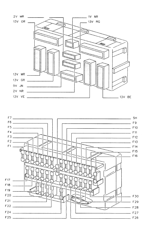
BF00 inside the cabin: Switch off the ignition and look under the dashboard on the driver’s side. On the applicable first-generation 406 fascia, undo the lower fuse-cover catch or quarter-turn retaining screws (the access hardware differs slightly by trim and revision) and carefully lower the panel. The inner legend identifies F1-F30 together with the auxiliary F1A and F16A positions and the bridging shunt at F8.
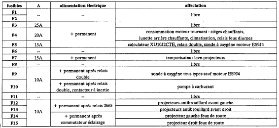
BF01 under the bonnet: Raise the bonnet and locate the covered engine fuse box beside the battery. Release the lid clips to expose positions F1-F15. The BMF1 and BMF2 high-current fuse modules are associated with the main power distribution in the engine compartment; verify the fitted module codes before removing a link. Some DW10 diesel engines also have a separate BMF3 block for additional heating. These links are not ordinary small blade fuses and need manufacturer-compliant servicing.
BF00 – thirty-fuse passenger-compartment board
This chart preserves the original BF00 assignments, including the F1A and F16A audio/backup feeds. F8 is a connecting shunt, not a current-rated replacement fuse. The first and sixteenth positions may have supplementary lettered supply variants. Some optional circuits in the table, such as rear wiper, electrically adjusted seats and LPG equipment, only exist on certain engines, body styles or markets.
| Pozycja | Amperaż [A] | Chroniony obwód / funkcja |
|---|---|---|
| F1 | 10 | Cigarette lighter on accessory-switched positive feed |
| F1A | 10 | Battery-positive radio/accessory backup feed. The original reference lists the supply but does not name a specific consumer |
| F2 | 10 | Coolant level, dashboard warning lamps, trip computer, speed signal, power steering module, catalytic converter temperature; diesel preheat, glow control, water-in-fuel and related engine sensors |
| F3 | 10 | ABS module, electronically controlled suspension ECU and switch, or LPG relays and valves on fitted cars |
| F4 | 5 | Left front and right rear parking/side lamps |
| F5 | 10 | Headlamp height adjustment, headlamp washer relay control, dipped beam warning and right dipped beam |
| F6 | 10 | Automatic gearbox ECU, gear selector switch and starter inhibit relay (4HP20), where fitted |
| F7 | 20 | Caravan/trailer accessory connector and diagnostic socket |
| F8 | Shunt | Electrical shunt connecting the specified circuits; it is not an ordinary fuse |
| F9 | 5 | Right front and left rear side lamps and lights-left-on buzzer |
| F10 | 30 | Electric seat and mirror position-memory controller |
| F11 | 30 | Power seat/mirror memory feed |
| F12 | 15 | Oil breather heater, reversing lamps, coolant control, stop lamps, alarm, remote door locking, cruise safety and automatic shift lock, depending on equipment |
| F13 | 30 | Passenger electric seat adjustment |
| F14 | 30 | Rear electric window motors |
| F15 | 20 | Engine cooling fan relay and control, seat/mirror memory module, alarm/IR remote central locking, radio memory, LPG circuit and Coupe deadlocking where fitted |
| F16 | 10 | Radio supply |
| F16A | 10 | Radio on accessory-switched feed |
| F17 | – | Unused fuse location |
| F18 | 5 | Rear fog lamps |
| F19 | 5 | Instrument cluster and switch illumination, clock, heater panel and dashboard dimmer |
| F20 | 10 | Left dipped-beam headlamp |
| F21 | 10 | Air-conditioning pressure switch and control ECU, ventilation ECU and cabin air temperature thermistor |
| F22 | 20 | Rear wiper, timed relay and rear passenger courtesy lamp on compatible estate/body variants; no rear wiper on saloon or Coupe |
| F23 | – | Unused position |
| F24 | 30 | Front wiper motor and timed control, front and rear washers, cruise control switch, optional rear wiper and rain sensor relay |
| F25 | 10 | Clock, instruments and trip computer, front and rear interior lighting, luggage lamp, injection/engine ECU and double relay, diesel EGR and injection solenoids, immobiliser and alarm equipment |
| F26 | 15 | Hazard warning lamps |
| F27 | 30 | One-touch electric window control |
| F28 | 10 | Trip computer, load-warning indicator, power mirror controls and folding mirrors, window motors/relays, seat memory, sunroof and clock |
| F29 | 30 | Electric front windows and optional sunroof relay supply |
| F30 | 15 | Front and rear courtesy lamps, vanity mirror and glovebox lamps, lights-left-on and overspeed buzzers, map lights, hazard switch, rain sensor, automatic gearbox safety and key-lock |
BF01 – engine compartment fuses F1-F15
The second box contains engine-control and accessory circuits including Pulsair air injection, automatic gearbox ECU, fuel pump, oxygen sensor, headlamp washers and front fog/main beam lights. F3, F6 and F8 are unused in this particular source configuration. BF01/F10 (10 A) covers the fuel pump after the inertia safety switch, while the relevant gearbox version uses F2 (10 A).
| Pozycja | Amperaż [A] | Chroniony obwód / funkcja |
|---|---|---|
| F1 | 25 | Pulsair secondary air injection pump on L4-emissions petrol versions |
| F2 | 10 | Automatic gearbox ECU and gear-selector position switch |
| F3 | – | Unused fuse location |
| F4 | 20 | Engine-running circuit for heated seats, rear demister, heating/ventilation and running-light relay |
| F5 | 15 | XU10J2CTE engine management unit, injection double relay and ES9J4 oxygen sensor control |
| F6 | – | Unused fuse position |
| F7 | 15 | Headlamp washer time-delay controller |
| F8 | – | Unused fuse position |
| F9 | 10 | Oxygen/lambda sensor supply after the double relay on engines other than ES9J4 |
| F10 | 10 | Fuel pump after the safety inertia switch |
| F11 | 15 | DW10 diesel engine equipment supplied after the double injection relay |
| F12 | 10 | Right front fog lamp |
| F13 | 10 | Left front fog lamp |
| F14 | 10 | Left high-beam headlamp |
| F15 | 10 | Right high-beam headlamp |
BMF1 – main 50 A power distribution fuses
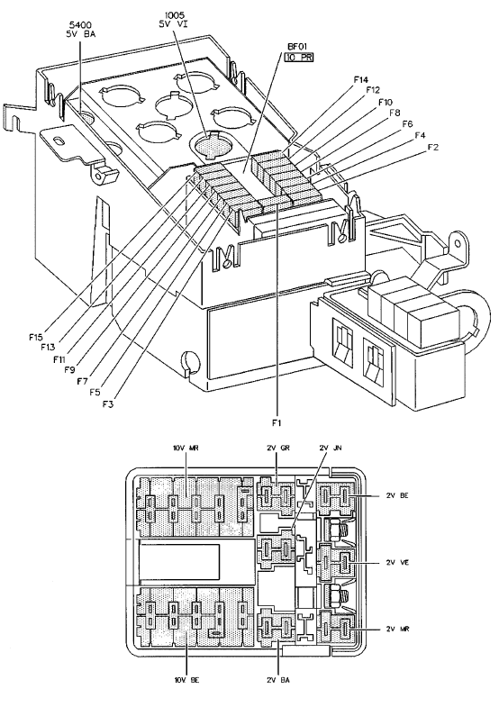
The four BMF1 links are all rated 50 A in the source configuration. They supply the steering/ignition lock, interior 30-position distribution and lighting/signalling equipment. A blown high-current link indicates a substantial fault or overload that should be traced before replacing the component.
| Pozycja | Amperaż [A] | Chroniony obwód / funkcja |
|---|---|---|
| MF1 | 50 | Steering column ignition/anti-theft lock main power feed |
| MF2 | 50 | Ignition switch and steering lock main circuit, including retained positive supply after switching off the ignition |
| MF3 | 50 | 30-fuse passenger-compartment BF00 main supply and lighting/signalling control |
| MF4 | 50 | Lighting/signalling switch, horn relay and driving lamp relay supplies |
BMF2 – ABS, cooling fan and rear-window heater
The source used two separate 20 and 40 A figures for each of MF6 and MF7 in a broken table layout. Technical references for the same box confirm these as 20 A or 40 A alternatives for different cooling-fan installations, not extra numbered positions. The two rows below therefore read 20 / 40 A, and the correct value depends on engine and cooling equipment. MF5 is the 50 A ABS supply; MF8 is 40 A for the heated rear screen and door mirrors.

| Pozycja | Amperaż [A] | Chroniony obwód / funkcja |
|---|---|---|
| MF5 | 50 | ABS main high-current power supply |
| MF6 | 20 / 40 | Cooling fan first power circuit, 20 A or 40 A according to the one-fan/two-fan and equipment-specific configuration |
| MF7 | 20 / 40 | Cooling fan second power circuit, 20 A or 40 A depending on factory fan configuration |
| MF8 | 40 | Heated rear window and electrically heated side mirrors |
BMF3 – supplementary DW10 diesel heating module
The original five-table source also lists an optional BMF3 high-current module with three 50 A links for additional electric heating on DW10 diesel engines. These positions are a separate heating supply, not an extra three slots inside the BMF2 radiator-fan carrier. The original article does not include an exact BMF3 location diagram, and no unverified picture from another configuration has been substituted.
| Pozycja | Amperaż [A] | Chroniony obwód / funkcja |
|---|---|---|
| MF1A | 50 | Additional electrical heater supply for DW10 diesel engine, first 50 A link |
| MF2A | 50 | Additional DW10 engine heater circuit, second 50 A link |
| MF3A | 50 | Additional DW10 engine heater circuit, third 50 A link |
DAM boundaries, market differences and cooling fan ratings
The 406 electrical system changed through production. Earlier DAM ranges may use different ratings for BF00 F2, F3, F5 and F6, and some later 406 vehicles have entirely different BSI fuse arrangements. For this DAM 7876-8420 variant, MF6 and MF7 can each be 20 or 40 A depending on the fitted radiator cooling system. That does not mean a car with a factory 20 A circuit can safely take a 40 A replacement.
Equipment such as active suspension, an automatic 4HP20 transmission, LPG, electric seats, sunroof, air-conditioning and DW10 auxiliary diesel heating adds or changes consumers. A saloon or Coupe without a rear tailgate wiper will not use an estate-only rear-wiper circuit despite a common fuse position on the printed reference.
Checking the lighter, fuel pump, wipers and headlamps
Cigarette lighter: BF00/F1 (10 A) provides the accessory positive feed in this older DAM configuration, whereas later 406 articles can assign a 20 A socket fuse elsewhere. Engine will not start: BF01/F10 (10 A) supplies the fuel pump after the inertia switch; also inspect injection relays and correct engine equipment. Front wipers fail: BF00/F24 (30 A) is associated with the front wiper and washer circuits.
Rear wiper: BF00/F22 (20 A) is intended for compatible estate wiring and need not serve the same load on a saloon. Dipped beam: BF00/F20 (10 A) protects the left lamp; BF00/F5 (10 A) includes right dipped-beam and headlamp-height/washer relay equipment. Heated rear screen fails: BMF2/MF8 (40 A) is the main high-current demister supply. Fan overheating: Match the actual 20/40 A ratings of MF6/MF7 and examine fan relays, sensors and wiring if the supply is intact.
Other Peugeot 406 fuse-box generations
The Peugeot 406 (2002-2004) saloon and Break has a later fuse-box arrangement and should not be used for this early DAM range. The Peugeot 406 Coupe (2002-2004) also has its own interior and engine box circuit ratings and different rear-body equipment. Compare model generation and production code before moving between these diagrams.
Technical basis: Peugeot 406 electrical technical reference for DAM 7876-8420, with BF00, BF01 and BMF1-BMF3 fuse carrier designations, and first-generation 406 technical repair diagrams. Fuse function, engine, market and production code can change the fitted assembly.