
This guide describes the earliest Peugeot 406 power distribution from VIN 80000001 up to production code DAM/ORGA 7135. The BF00 fascia carrier, BF01 engine compartment fuse panel and Maxi block together comprise 55 distinct fuse and shunt positions. It does not apply unchanged to later 406 vehicles: the 7136-7323 (7510) series changes several amperages and circuit assignments.
What do the Peugeot 406 DAM and ORGA numbers mean?
DAM/ORGA is the manufacturer’s production code, not necessarily the year shown on the registration document. Locate the code on the original Peugeot vehicle identification label or retrieve it from VIN-based service information. The ranges used in these documents correspond to specific electrical build arrangements. A visual comparison of the fitted fascia and under-bonnet panel is essential, particularly if a replacement harness or electrical box has been installed over the years.
Peugeot 406 fuse box locations and access
Passenger compartment BF00: Turn off the ignition. On a left-hand-drive vehicle, look under the lower dashboard beside the steering column. Depending on trim, undo the panel’s retaining catches or quarter-turn fasteners and tilt the cover to access the 30-fuse board. The fuse puller is typically stored in the cover. Verify the position numbers on the installed board, not on another model-year legend.
Engine compartment BF01: Open the bonnet and find the covered electrical distribution box near the battery. Unclip its cover carefully. The smaller F1-F15 fuses protect fuel supply, injection, ABS, lighting and optional equipment.
Maxi high-current carrier: The MF1-MF8 power links are mounted with the engine compartment power distribution, potentially in multiple associated blocks. They protect the ignition supply, dashboard feeder, ABS, engine cooling and heated rear screen. Large links require appropriate electrical service procedures; do not fit a higher rating to prevent a fuse from blowing.
BF00 – 30-position passenger-compartment fuse box
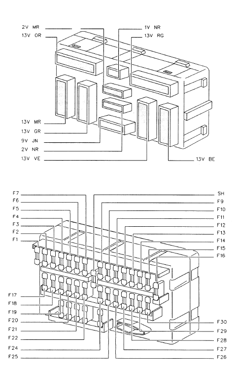
F8 is a connecting shunt, not a conventional fuse. BF00 F1 and F1A refer to accessory-switched and battery-positive feeds and are each 10 A in this old specification. Right and left dipped beams are not protected by the same ratings here: the original chart lists BF00 F20 at 30 A and BF00 F23 at 10 A. These unusual early values must be checked on the actual panel rather than silently replaced with values from a facelifted model. The first illustration is a first-generation BF00 carrier layout reference; the specific ratings below are for this DAM range, not a universal fuse list for every Peugeot 406.
| Pozycja | Amperaż [A] | Chroniony obwód / funkcja |
|---|---|---|
| F1 | 10 | Cigarette lighter on accessory-switched positive supply (ACC+) |
| F1A | 10 | Battery-positive back-up feed for the cigarette lighter / related accessory connection |
| F2 | 15 | Engine coolant level and diesel water-in-fuel sensors, instrument warning lights, trip computer and speed-signal interface |
| F3 | 15 | Anti-lock braking system (ABS) electronic control module |
| F4 | 10 | Left front and right rear side / parking lights |
| F5 | 15 | Headlamp beam height correction, headlamp washer relay coil and dipped beam warning lamp |
| F6 | – | Unused position in this early panel |
| F7 | 20 | Caravan and trailer accessory power connector |
| F8 | Shunt | Electrical link / shunt; not a replaceable amperage-rated fuse |
| F9 | 5 | Right front and left rear side / parking lights |
| F10 | 30 | Powered seat and exterior mirror memory module |
| F11 | 30 | One-touch electric window control module |
| F12 | 10 | Oil-breather heater, reversing lights and engine coolant temperature / A/C control circuits |
| F13 | 20 | Electric passenger seat adjustment |
| F14 | 20 | Electric driver’s seat adjustment |
| F15 | 20 | Alarm control, radio telephone, cooling fan relay, engine temperature controller and seat/mirror memory unit |
| F16 | 20 | Radio supply |
| F16A | 20 | Accessory-switched radio supply (additional F16A position) |
| F17 | – | Unused location |
| F18 | 10 | Rear fog lamps |
| F19 | 10 | Instrument and dashboard switch illumination |
| F20 | 30 | Left dipped-beam headlamp in this early fuse-box allocation |
| F21 | 30 | A/C compressor cut-off relay, pressure switch, cooling fan relay and heating/ventilation controls |
| F22 | 30 | Estate rear wiper and its timed relay, on vehicles with that equipment |
| F23 | 10 | Right dipped-beam headlamp in this early fuse-box allocation |
| F24 | 30 | Front windscreen wipers, timed wiper controller and rear-window heater timer |
| F25 | 5 | Radio/CD memory, clock, instruments, trip computer, coded anti-start device and parking lamps |
| F26 | 30 | Hazard warning lamps |
| F27 | 30 | One-touch power window circuit |
| F28 | 15 | Trip computer, load warning, mirror/seat memory and electric window controls, central locking receiver, sunroof relay, stop lamps and digital clock |
| F29 | 30 | Front electric windows and optional sunroof relay |
| F30 | 15 | Front and rear courtesy lamps, vanity mirror and glovebox lights, warning buzzers and optional radio-telephone equipment |
BF01 – under-bonnet fuses F1-F15
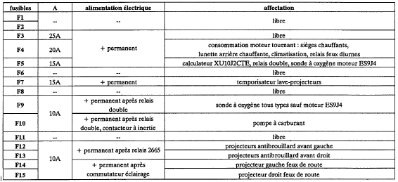
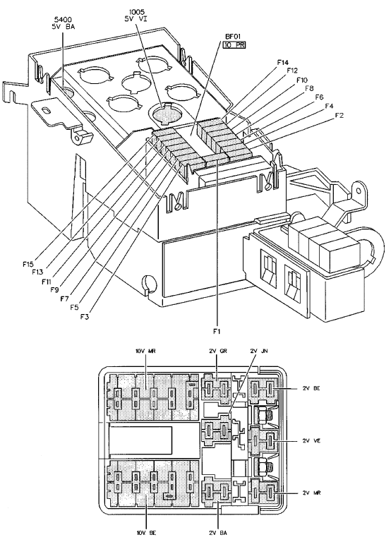
The BF01 list retains all fifteen sockets and the early equipment variations. Position F1 shows two manufacturer-list ratings, 5 A or 7.5 A, for engine injection electronics. It is one numbered socket with different variant specifications, not two simultaneous F1 fuses. BF01 F3 is 25 A for ABS/traction equipment. Positions F2, F6, F8 and F11 are unused; F10 is the 10 A fuel pump feed. This diagram shows the relevant BF01 carrier layout; circuit assignment follows the separate DAM-specific table.
| Pozycja | Amperaż [A] | Chroniony obwód / funkcja |
|---|---|---|
| F1 | 5 / 7.5 | Petrol/diesel injection electronic controller supply; 5 A or 7.5 A alternative according to the early wiring specification |
| F2 | – | Unused fuse position |
| F3 | 25 | ABS and traction control supply |
| F4 | 20 | Battery-powered engine-running auxiliary circuit |
| F5 | 7,5 | XUD11ATE engine relay and management feed |
| F6 | – | Unused location, even where battery supply is present at the carrier |
| F7 | 15 | Headlamp washer time-delay relay |
| F8 | – | Unused location |
| F9 | 10 | Oxygen / lambda sensor |
| F10 | 10 | Fuel pump |
| F11 | – | Unused position |
| F12 | 10 | Left front fog lamp feed after relay 2665 |
| F13 | 10 | Right front fog lamp |
| F14 | 10 | Left main-beam headlamp after lighting switch |
| F15 | 10 | Right main-beam headlamp |
Maxi fuse links MF1-MF8
The factory-style high-current group contains eight numbered MF positions. MF1-MF5 are 50 A in this early type; MF8 is 40 A for rear-window heating. The source has broken line wrapping at MF6 and MF7, showing separate 20 and 40 A figures. These are 20 / 40 A alternative cooling-fan ratings at the same two positions, not four separate fuses. Use the vehicle’s factory cooling-system specification. The diagrams show associated first-generation high-current carrier modules.

| Pozycja | Amperaż [A] | Chroniony obwód / funkcja |
|---|---|---|
| MF1 | 50 | Steering column / ignition-lock main power supply |
| MF2 | 50 | Steering column / ignition-lock additional positive supply |
| MF3 | 50 | Power feed for the 30-fuse BF00 passenger-compartment electrical panel |
| MF4 | 50 | Lighting/signalling switches and horn relay main circuit |
| MF5 | 50 | ABS and traction control main high-current supply |
| MF6 | 20 / 40 | Cooling-fan supply, 20 A or 40 A depending on factory single-/dual-fan installation |
| MF7 | 20 / 40 | Second radiator cooling-fan supply, 20 A or 40 A for the relevant cooling system |
| MF8 | 40 | Heated rear windscreen main supply |
Important differences between DAM and engine specifications
The early BF00 uses F2 at 15 A for sensor and instrument circuits, F3 at 15 A for ABS, F4 at 10 A and F5 at 15 A. F6 is unoccupied in this configuration. On the BF01 engine board the injection ECU feed is F1 at 5 A or 7.5 A depending on the precise early wiring variant, and ABS/traction supply is F3 at 25 A. The 7136-7323 specification instead includes a 15 A automatic gearbox feed at BF00 F6, and lowers BF00 F2 and F3 to 10 A, among other changes.
Manual or automatic gearbox, ABS/traction control, powered and memory seats, air conditioning, estate rear wiper, petrol injection or diesel engine controls affect the installed circuit. MF6 and MF7 change according to fan assembly specification. The same fuse position number can correspond to a different current rating in the neighboring DAM range, so confirm the exact vehicle before installing an electrical replacement.
Fault diagnosis using the correct fuse board
Cigarette lighter: Check BF00 F1 (10 A) and its accessory-switched positive feed, along with the separate F1A supply where relevant. Fuel pump: BF01 F10 (10 A). Wipers: BF00 F24 (30 A). Heater blower and A/C: Examine BF00 F21 (30 A) and the associated fan relays. Left dipped beam: BF00 F20 (30 A in this earliest chart); right dipped beam: BF00 F23 (10 A). Check the actual build specification before fitting replacements.
Cooling fan does not start: Inspect Maxi MF6/MF7 only after verifying whether the vehicle uses the 20 A or 40 A fan supply design, then check fan relays, coolant temperature equipment and motor wiring. Heated rear glass fails: Maxi MF8 (40 A) supplies the heating circuit. An intact fuse does not rule out a broken heating element or corroded wiring.
Related Peugeot 406 fuse box guides
For the neighboring early-series layout, compare Peugeot 406 DAM 7136-7323 (7510). The Peugeot 406 DAM 7876-8420 fuse diagram shows another electrical revision, while the Peugeot 406 (2002-2004) uses later fuse-box equipment. Never mix ratings or relay functions across those production ranges.
Technical sources: early Peugeot 406 electrical fuse-application charts for this VIN/DAM range, cross-checked against the first-generation Peugeot 406 technical fuse documentation. The illustrations show fuse-carrier form, while circuit ratings are specific to the named production interval.