
The Peugeot 306 (1993-2002) was built as an N3/N5 hatchback, four-door saloon, Break estate and Cabriolet, with significantly different electrical installations. Its original Polish reference contains three types of cabin fuse panel, several under-bonnet fuse arrangements and two relay lists. The complete 123 technical positions and relays are preserved below. Two separate overview grids are presented as mobile-friendly cross-reference text, so no fuse, relay, unused socket or amperage has been silently dropped.
Frequently checked fuses – comparison across three panel families
This comparison reproduces all ten functions in the source overview. These are alternative installations, not concurrent assignments: first identify the actual panel, then use the matching technical table below.
Cigarette lighter: Early 13-fuse boards: normally F8 (20 A), but other wiring uses F9, F10 or F17. BF30: F16 or F16A (20 A). Later 28-fuse: No. 23 (20 A).
Radio: Early boards: F8 or F9 according to the installation. BF30: F1, F1A and F25. 28-fuse: F8 and F24 or F25 according to body style.
Horn: Early boards: F8, F9 or F10 according to layout. BF30: usually F7 (20 A). 28-fuse: No. 17 (20 A).
Front wipers: Early boards: often F9 (30 A). BF30: F24 (30 A). 28-fuse: No. 26 (30 A).
Rear wiper: Early boards: F4 or F12, according to the panel variant. BF30: F22 or F24. 28-fuse: No. 28 (15 A).
Rear window heater: Early boards: F3 or F5. BF30: F27 (30 A). 28-fuse: No. 7 (30 A).
Heater blower: Early boards: F2, F4 or F10 depending on wiring. BF30: F21 (25 or 30 A). 28-fuse: No. 20 (30 A).
Front fog lamps: Early boards: depends on the installed fuse carrier. BF30: F6 (10 A). 28-fuse: No. 18 (10 A).
Petrol fuel pump: Early cars: depends on engine and pump relay arrangement. One BF30-era under-bonnet panel: F35 (10 A). Later under-bonnet arrangement: F35 (15 A).
Dipped beams: Early engine panels: confirm physical layout rather than assuming a universal location. BF30-era system: F14/F15 on certain engine panels or separate relays. Later 28-fuse system: under-bonnet 29 and 30 (10 A each).
How to identify the correct Peugeot 306 fuse-board variant
Early 13-fuse carrier: one or several short rows, with F1-F13 and sometimes additional empty sockets up to F17; found on early N3 and selected simpler configurations. BF30: F1-F30 plus optional F1A and F16A, widely used either side of the 1997 facelift. Later 28-fuse fascia unit: numbered 1-28 without F and with a passenger-compartment protection module, typically on cars from the late 1990s.
The Peugeot DAM/ORGA production identifier gives a more accurate electrical build reference than the registration year alone. It is usually recorded on a factory sticker in the door pillar or engine bay and in VIN-linked service data. Known variant breakpoints in the Polish source include DAM 7147-7447, 7693-8210 and 8211 onward; older entries are also separated by VIN series. Do not interpret partial VIN numbers as universally increasing chronological ranges across all factories. The physical fuse cover and factory documentation for the actual VIN are decisive.
Peugeot 306 fuse box locations
Passenger compartment: Switch off the ignition and look below the driver’s side of the dashboard on a left-hand-drive Peugeot 306. On the later fascia version, turn the retaining catch one quarter-turn with a coin and remove the access flap. The fuse puller is normally fixed to the cover. On early carriers, the shape of the flap and the board position can differ, so check the installed panel and clips without forcing old plastic parts.
Engine compartment: Open the bonnet and locate the covered power-distribution box near the battery. Release the plastic retaining clips to reach the engine fuses, cooling-fan feeds and main links. Some older versions use additional auxiliary holders or relays near the front of the engine bay and radiator. Confirm the exact wiring before handling high-current links and ensure the cover seals correctly afterwards.
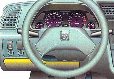
Early Peugeot 306 – 13-position cabin fuse panel
This is a 13-entry version of the early fascia panel. It is not universal across 1993-1997 or even among cars registered in the same year. Fuses 8-10 are frequently queried for the lighter, wipers and blower but the exact assignment changes with the different early layouts. This table retains the 13 fuses and ratings as published in the specific source diagram.
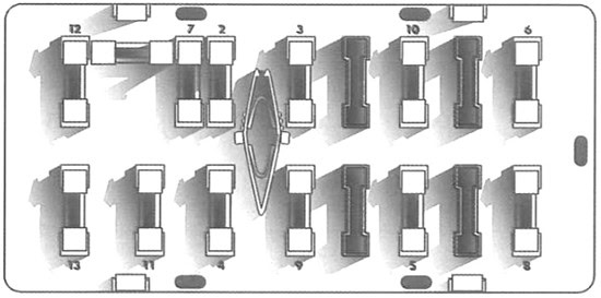
| Pozycja | Amperaż [A] | Chroniony obwód / funkcja |
|---|---|---|
| F1 | 10 | Lights-left-on buzzer, switch illumination, cigarette-lighter illumination and instrument-panel backlighting |
| F2 | 25 | Heater or air-conditioning blower motor |
| F3 | 25 | Rear window heating, heated mirrors or heated seats, depending on factory equipment |
| F4 | 15 | Turn signals and rear windscreen wiper |
| F5* | 30 | Rear window and exterior mirror heating, or associated timed relay depending on fuse-board version |
| F6 | 10 | Engine control module and hazard warning lights |
| F7 | 10 | Reversing lamps, instrument warning indicators, fuel level and immobiliser, depending on vehicle specification |
| F8 | 20 | Courtesy and luggage-compartment lighting, clock, radio memory, cigarette lighter and immobiliser |
| F9 | 30 | Brake lamps, charging warning lamp, interior lighting, lights-on warning, front wiper/washer and radio |
| F10 | 25 | Radiator fan, climate-control circuits, horn or cigarette lighter depending on the version of the early fuse board |
| F11 | 5 | Rear fog lamp and exterior lighting switch |
| F12 | 7.5 | Right-hand rear side/parking lamp |
| F13 | 15 | Front position lamps, left rear side lamp and registration-plate lighting |
Peugeot 306 BF30 – passenger panel F1-F30, F1A and F16A
Many vehicles use a BF30 carrier with additional A-suffixed fuse positions. F8 is an electrical linking shunt, not a standard amperage-rated fuse. Position F16 can supply a permanently live 20 A lighter and F16A a 20 A accessory-switched lighter depending on the installation. Options such as an automatic gearbox, sunroof, heated seats, front and rear electric windows and the Cabriolet folding roof alter the occupied sockets and ratings.
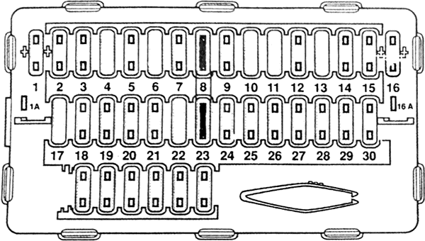
| Pozycja | Amperaż [A] | Chroniony obwód / funkcja |
|---|---|---|
| F1 | 10 | Radio on accessory-switched supply |
| F1A | 10 or – | Optional permanent radio supply and memory feed; this socket is not fitted to every BF30 panel |
| F2 | 5 | Instrument indicators, tachometer, fuel/coolant gauges, immobiliser and optional automatic transmission selector illumination |
| F3* | 15 or – | Cooling fan relay and A/C pressure switch or compressor cut-out relay; unused on alternative installations |
| F4 | 10 | Front position lights and right-hand rear position lamp |
| F5 | 10 | Heater fan control, A/C pressure switch, fan and compressor relays, or heated rear-window timer |
| F6 | 10 | Front fog lamps |
| F7 | 20 | Horn, radiator fan control, coolant thermostat, lighting and alarm systems, depending on wiring variant |
| F8 | Shunt | Electrical shunt connecting supply circuits F15 and F25; not a standard blade fuse |
| F9 | 5 | Left rear position lamp, registration plate lamps and switch, radio and lighter illumination |
| F10 | 30 | Rear electric window motors |
| F11 | 30 or – | 306 Cabriolet electric folding-roof equipment, or unoccupied in other bodies |
| F12* | 10 or 20 | Reversing lights, ABS, starter lockout, water-in-fuel warning, cruise control, air-conditioning, cooling fan or headlamp relay control depending on installation |
| F13 | 15 or – | Hazard warning lamp circuit, or unoccupied on some equipment levels |
| F14 | 15 or – | Central locking, immobiliser or anti-theft dipped-beam relay, depending on vehicle specification |
| F15* | 20 or 30 | Hazard warning lamps, interior/boot lamps, locking/alarm, infrared receiver, engine control or cooling fan power supply |
| F16 | 20 | Cigarette lighter supplied permanently by battery positive |
| F16A | 20 | Cigarette lighter on accessory-switched power supply |
| F17 | 20 or – | Central locking, deadlocking, alarm or unoccupied on some vehicles |
| F18 | 10 | Rear fog lamp |
| F19 | 10 | Hazard switch, clock, lighter, instrument and A/C control-panel illumination |
| F20 | 30 or – | Heated front seats if equipped; otherwise the socket may be unused |
| F21* | 25 or 30 | Heater and air conditioning blower, flap motors and interior temperature sensor; the fuse can be 25 A or 30 A |
| F22 | 20 | Rear wiper, central locking, utility-van accessory lighting or rear-window relay |
| F23* | 5 or Shunt | Rear window and mirror heating controls, cabin temperature sensor, or a linking shunt, depending on wiring |
| F24 | 30 | Front and rear wipers plus windscreen and headlamp washer pumps |
| F25 | 5 | Clock, radio memory, alarm warning lamp, luggage lighting and instrument memory supply |
| F26 | 20 or – | Power antenna and trailer wiring, or an unused slot depending on version |
| F27 | 30 | Rear window defogger and heated mirrors |
| F28 | 15 | Brake lamps, electric windows, sunroof, clock, warning indicators or 306 Cabriolet roof system |
| F29 | 30 | Front power windows, sunroof or part of the convertible roof electrical system |
| F30 | 15 | Turn indicators, interior/map lamps, powered mirrors, infrared central-lock receiver, electric windows and optional rain sensor |
Production-specific BF30 ratings: Peugeot wiring references give F12 as either 10 or 20 A, F15 as 20 or 30 A and F21 as 25 or 30 A. These are different configurations, not permission to replace a blown fuse with a higher amperage. The 1997-1999 diagram and alternative DAM/VIN-based documentation do not always use identical values.
Later Peugeot 306 – 28-position passenger panel
The later under-dashboard fuse box has positions numbered 1-28 rather than F1-F30. It includes separately protected electric windows, demister, wiper and lighting circuits. An original Peugeot 306 owner’s manual lists the same 28-position fascia system, including the 7.5 A automatic-transmission or speed-warning circuit at position 2 and the 20 A lighter circuit at position 23. Optional Cabriolet roof functions are explicitly identified below.
| Pozycja | Amperaż [A] | Chroniony obwód / funkcja |
|---|---|---|
| 1 | – | Unused position in the 28-fuse fascia panel |
| 2 | 7.5 | Automatic gearbox controller or overspeed warning buzzer, depending on market |
| 3 | 5 | Anti-lock braking system control unit |
| 4 | 5 | Instrument cluster, cabin protection unit, coolant temperature control, automatic selector illumination and relay or passenger airbag cut-off switch |
| 5 | 25 | Reversing and stop lamps, automatic transmission relay, daytime running lamp relay, radiator fan relay and A/C pressure switch / compressor |
| 6 | 5 | Instrument cluster, cabin protection unit, alarm warning light, clock, boot lamp and power aerial |
| 7 | 30 | Rear-window heater and exterior mirror demisting |
| 8 | 20 | Passenger-compartment protection controller and audio equipment |
| 9 | 20 | Engine injection controller, cooling fan relay and coolant temperature electronics on equipped engines |
| 10 | 20 | Hazard warning lamps plus front and rear courtesy lights |
| 11 | 10 | Instrument backlighting, side-light warning buzzer, clock, dimmer and parking lamps |
| 12 | 10 | Rear fog lamp |
| 13* | – or 30 | Not used on hatchback and estate versions; 30 A convertible roof relay on applicable 306 Cabriolet |
| 14 | 30 | Rear electric windows and heated seat relay |
| 15 | 20 | Trailer towing connector supply |
| 16 | 30 | Front electric window and sunroof relay, including Cabriolet electric windows where fitted |
| 17 | 20 | Horn |
| 18 | 10 | Front fog lamps |
| 19 | 10 | Right rear position lamp |
| 20 | 30 | Heater and air-conditioning blower motor |
| 21 | 10 | Left rear position lamp, registration-plate light and front parking lamps |
| 22 | 10 | Ventilation relay and control for rear window / mirror demisting |
| 23 | 20 | Cigarette lighter |
| 24* | – or 10 | Unused on certain hatchbacks, or radio supply at 10 A on the relevant convertible variant |
| 25* | 10 | Radio supply on hatchback and estate; Cabriolet may use this position for roof or A/C control |
| 26 | 30 | Front wiper switch/motor, timed relay, washer pump and rain-sensor equipment |
| 27 | 15 | Glovebox and map lamps, turn signals, electric mirrors, vanity mirror lights, rain sensor and cabin temperature sensor |
| 28 | 15 | Clock, outside temperature display, window/heated-seat relays, rear wiper, sunroof and Cabriolet equipment |
Older engine-bay auxiliary fuse holder – F31-F36
This separate six-position engine-bay holder belongs to some BF30-era installations and must not be combined with the later F1-F15 or 29-40 main box. The F32 position is a shunt. Fan circuits F33 and F34 may be 30 or 40 A, whereas F35 is 10 A in this particular arrangement. Later engine panels can label the fuel pump F35 at 15 A instead.
| Pozycja | Amperaż [A] | Chroniony obwód / funkcja |
|---|---|---|
| F31 | 30 | ABS power supply |
| F32 | Shunt | Main feed bridging shunt; not a standard replaceable fuse |
| F33* | 30 or 40 | Radiator cooling fan and associated warning/control circuits, 30 A or 40 A by version |
| F34* | 30 or 40 | Second engine cooling fan supply, 30 A or 40 A by version |
| F35 | 10 | Fuel pump circuit in this particular engine panel, 10 A |
| F36 | 30 | Lambda / oxygen sensor heater or associated engine management circuit |
Engine compartment – alternative F1-F15 board
The fifteen-position engine panel has separate cooling fan and headlamp circuits. The source diagram lists F2 and F3 at 40 A, F9 as the fuel pump supply (15 A) and positions F12-F15 for left/right high and low beam lights. F6 at 20 A is model-dependent; verify its actual description on the vehicle’s cover.
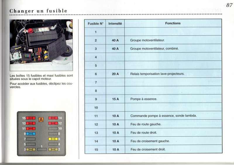
| Pozycja | Amperaż [A] | Chroniony obwód / funkcja |
|---|---|---|
| F1 | – | Unused position |
| F2 | 40 | First radiator cooling fan circuit |
| F3 | 40 | Second radiator cooling fan circuit |
| F4 | – | Unused position |
| F5 | – | Unused position |
| F6* | 20 | Engine- and market-dependent supply; identify its function from the installed cover, not from another model |
| F7 | – | Unused position |
| F8 | – | Unused position |
| F9 | 15 | Fuel pump |
| F10 | – | Unused position |
| F11 | 10 | Fuel pump control and oxygen sensor |
| F12 | 10 | Left high-beam headlamp |
| F13 | 10 | Right high-beam headlamp |
| F14 | 10 | Left dipped-beam headlamp |
| F15 | 10 | Right dipped-beam headlamp |
Later high-current supply links – MF1-MF4
In later 306 power distribution, four high-current links protect the ignition or anti-theft supply, the main cabin electrical circuits and ABS. Their values are 40, 60, 60 and 60 A in this source configuration. Peugeot service documentation recommends professional attention to Maxi links; unlike normal fuse blades they may require dedicated access and removal procedures.
| Pozycja | Amperaż [A] | Chroniony obwód / funkcja |
|---|---|---|
| MF1* | 40 | Main ignition switch or anti-theft supply, according to wiring reference and engine |
| MF2 | 60 | Power supply for locking, lighting switch, A/C blower, front fog lamp relay and diagnostic connector |
| MF3 | 60 | ABS main control module power |
| MF4 | 60 | Permanent power feed to the passenger compartment fuse box |
Later engine compartment – fuses 29-40
This group forms part of the later 28-fuse cabin system’s corresponding engine distribution. Headlights are split into 29-32 (10 A each), and petrol pump position 35 is 15 A. Position 33 may protect a diesel controller but be unused on certain petrol models, while position 39 is a spare or alternative cooling circuit. Source tables and some online references differ about how position 40 is assigned; the Peugeot owner’s handbook lists a 40 A fan unit circuit, so the fitted legend takes precedence.
| Pozycja | Amperaż [A] | Chroniony obwód / funkcja |
|---|---|---|
| 29 | 10 | Left dipped-beam headlamp |
| 30 | 10 | Right dipped-beam headlamp |
| 31 | 10 | Left main-beam headlamp |
| 32 | 10 | Right main-beam headlamp |
| 33 | 15 or – | Diesel engine control unit, or unused on petrol / Cabriolet variants |
| 34 | 10 | Oxygen / lambda sensor |
| 35 | 15 | Petrol fuel pump |
| 36 | 20 | Headlamp washer timer on equipped vehicles |
| 37 | 40 | Engine radiator cooling fan assembly |
| 38 | – | Unused fuse position |
| 39 | 40 | Spare high-current cooling fan link or alternative fan circuit depending on model |
| 40 | 40 | Engine cooling fan assembly |
Peugeot 306 passenger and engine relay modules
Relay locations do not follow a single universal numbered carrier across all years. The following descriptions retain all relay functions in the source, including electrically powered convertible roof equipment, which does not belong to hatchback, saloon or Break versions.
Relays inside the passenger compartment
| Pozycja | Amperaż [A] | Chroniony obwód / funkcja |
|---|---|---|
| – | – | Heater and air-conditioning blower relay. |
| – | – | Rear window and heated mirror demister relay or time-delay module. |
| – | – | Electric window relays, front and rear and one-touch window operation. |
| – | – | Front heated seat relay. |
| – | – | Central locking / deadlocking relay. |
| – | – | Timed wiper relay or rain-sensor control module. |
| – | – | Electric convertible roof motor relay on Peugeot 306 Cabriolet only. |
Relays under the bonnet
| Pozycja | Amperaż [A] | Chroniony obwód / funkcja |
|---|---|---|
| – | – | Low- and high-speed engine cooling fan relays. |
| – | – | Petrol fuel pump relay. |
| – | – | Air-conditioning compressor clutch and automatic cut-out relay. |
| – | – | Headlamp washer motor relay where fitted. |
| – | – | Dipped-beam, main-beam or daytime-running-light relays, according to market. |
| – | – | Diesel glow-plug preheating controller or relay. |
Body style, engine and equipment differences
Hatchback and saloon: The rear-wiper supply is not required on saloon vehicles without a tailgate wiper. Central locking modules, body protection electronics and rear lamp wiring differ by installation. Break estate: Rear washer/wiper supply and luggage-compartment lighting can alter fuse function at otherwise similar positions.
Cabriolet: Folding roof relays, window interlocks and extra high-current consumers require the actual Cabriolet wiring variant. A relay or fuse that is unused on a hatchback can be populated on the Cabriolet. Petrol: The fuel pump and oxygen sensor circuits are present on appropriate engine management variants. Diesel: Preheating controls and diesel ECU supplies differ from petrol wiring; this includes some of the later positions 33 and 35. Air conditioning: Fan relay and blower fuse allocations often change when air conditioning is factory fitted.
Diagnosing typical Peugeot 306 electrical faults
Cigarette lighter: Identify whether the car has an early panel (often F8), BF30 (F16 or F16A, 20 A), or later 28-position panel (No. 23, 20 A). Radio: BF30 has several switched and permanent feeds (F1, optional F1A and F25); the 28-fuse version uses its own passenger-compartment protection unit and audio circuits.
No cabin blower: Check F2 (25 A) in the matching early 13-fuse panel, F21 (25/30 A according to BF30 variant) or No. 20 (30 A) on the later 28-position board. If only one fan speed operates, test the speed regulator/resistor and connections. Wipers fail: Compare early F9 (30 A), BF30 F24 (30 A), or later No. 26 (30 A), then inspect the motor and intermittent relay.
Rear demister: Typical locations are early F3/F5, BF30 F27 (30 A) or later No. 7 (30 A). One dipped beam fails: The later under-bonnet box uses 29 and 30, each 10 A; the alternative F1-F15 panel instead uses F14/F15. Cooling fan: Do not assume 30 and 40 A are interchangeable for F33/F34: inspect the relays, fan and temperature control wiring. Engine will not start: On petrol engines verify the pump supply appropriate to the installed engine panel, relays and immobiliser before replacing components. Diesel cold-start faults also call for inspection of glow-plug and preheating circuits.
Related Peugeot fuse diagrams
For the contemporary larger model, see the Peugeot 406 Coupe (2002-2004), which has a different electrical layout despite sharing some PSA components. The Peugeot 205 late fuse diagram and Peugeot 106 II cover smaller models from adjacent generations but are not interchangeable with the 306.
Technical basis: Peugeot 306 N3/N5 owner’s manual, fuse system and maintenance sections; Peugeot electrical documents and the original comprehensive Polish 306 article. Select the correct set by fuse-panel design, VIN/DAM/ORGA, engine, market and body style.