
The Peugeot 807 (2002-2014) has three fuse locations and several year-specific electrical installations. This guide contains the full 183 rows in 11 tables, including five original box-identification references, 24 fault lookups, three dashboard board versions, earlier and later battery and engine charts, and separate Maxi link assignments. The earlier tables must never be combined with the later fuse carrier simply because fuse numbers repeat.
Fuse locations and access in the Peugeot 807
Cabin: In left-hand-drive 807s the dashboard carrier is inside the lower glovebox on the right-hand passenger side, not under the driver’s steering column. Switch ignition off, open the lower compartment and release its fuse cover. On right-hand-drive cars the unit is under the dashboard on the driver’s side. Use the supplied fuse extractor and the layout corresponding to the actual fitted carrier.
Battery: Lift the floor panel ahead of the right-hand front seat and open the battery-compartment fuse lid. This separate holder carries power feeds for optional electric sliding doors, electrically adjustable seats and second/third-row sockets. Engine: Open the bonnet and locate the fuse unit to the left of the coolant expansion reservoir. Unclip its cover, inspect the labeled positions and reseal it fully after checking. High-current Maxi links require approved workshop procedures.
Three different Peugeot 807 dashboard variants
The early board can be identified by the front lighter at position 7 (20 A) and rear defroster at 26 (40 A). A separate 2006-2009 style uses F16 (20 A) for the lighter and F24 (30 A) for front wash/wipe power. The 2010-2014 board lists the lighter as 9 (30 A) and rear heater as 17 (40 A). Match the original printed physical board before using any fuse value.
| Pozycja | Amperaż [A] | Chroniony obwód / funkcja |
|---|---|---|
| D1 | – | Early dashboard, 2002-2005, lighter fuse 7 and demister fuse 26 |
| D2 | – | Alternative dashboard, 2006-2009, lighter F16 and wiper F24 |
| D3 | – | Late dashboard, 2010-2014, lighter 9 and rear heater 17 |
| BAT | – | Underfloor battery carrier on right front passenger side, sliding doors and rear 12V sockets |
| ENG | – | Under-bonnet carrier left of coolant reservoir, horn, lights, engine and ABS |
Popular fuses and electrical consumers
The 24 Q labels below are editorial lookup numbers, not manufacturer fuse positions. The third column retains all source fuse codes and box locations. The front lighter can be 7, F16 or 9; the second-row 12 V socket uses battery-floor 40 (20 A), and the third-row socket uses 39 (20 A).
| Pozycja | Amperaż [A] | Chroniony obwód / funkcja |
|---|---|---|
| Q01 | 20 / 20 / 30 | Front lighter: 7 / F16 / 9; Zależnie od typu skrzynki pod deską rozdzielczą. |
| Q02 | 20 | Second-row 12V socket: 40; Skrzynka przy akumulatorze. |
| Q03 | 20 | Third-row 12V socket: 39; Skrzynka przy akumulatorze. |
| Q04 | 10-20 | Audio and radio: 11 / 20 / F1 / F25 / 8; Zależnie od typu skrzynki i wyposażenia. |
| Q05 | 30 | Hi-Fi amplifier: 3; Skrzynka przy akumulatorze. |
| Q06 | 15 | Rear wiper: 2 / 1; Skrzynka pod deską rozdzielczą. |
| Q07 | 30 | Front wipers: 17 / F24 / 12; Komora silnika albo typ 2 skrzynki pod deską. |
| Q08 | 10 | Window wash pumps: 14 / 3; Skrzynka w komorze silnika. |
| Q09 | 20 | Headlight washers: 7 / 4; Komora silnika. |
| Q10 | 15 / 15 / 20 | Horn: 13 / 2 / F7; W zależności od typu skrzynki. |
| Q11 | 10 | ABS/ESP: 3 / 7 / F12; Komora silnika lub typ 2 skrzynki pod deską. |
| Q12 | 15 | Fuel pump: 2 / 5; Komora silnika, zależnie od wersji silnika. |
| Q13 | 15 | Left dipped beam: 9; Komora silnika, typ 1. |
| Q14 | 15 | Right dipped beam: 10; Komora silnika, typ 1. |
| Q15 | 10 | Left main beam: 11; Komora silnika, typ 1. |
| Q16 | 10 | Right main beam: 12; Komora silnika, typ 1. |
| Q17 | 30-40 | Heated rear glass: 26 / F27 / 17; Zależnie od typu skrzynki. |
| Q18 | 15-30 | Front power windows: 9 / F28 / F29 / 5 / 6; Zależnie od typu skrzynki. |
| Q19 | 30 | Rear power windows: 15; Skrzynka pod deską, typ 1. |
| Q20 | 30 | Central locking: 14 / F15 / 15 / 16; Zależnie od typu skrzynki. |
| Q21 | 40 | Right power sliding door: 1; Skrzynka przy akumulatorze. |
| Q22 | 40 | Left power sliding door: 2; Skrzynka przy akumulatorze. |
| Q23 | 25 | Driver power seat: 32; Skrzynka przy akumulatorze. |
| Q24 | 25 | Passenger power seat: 33; Skrzynka przy akumulatorze. |
Early dashboard carrier, usually 2002-2005
The original early dashboard contains all positions 1-26, including unused 3, 6, 8, 13, 21 and 25. The front lighter and reading lamps are 7 (20 A), rear wiper 2 (15 A), front windows and roof 9 (30 A) and heated rear screen 26 (40 A). Position 19 is a PARC transport-mode shunt even though the source chart prints a 40 A entry.
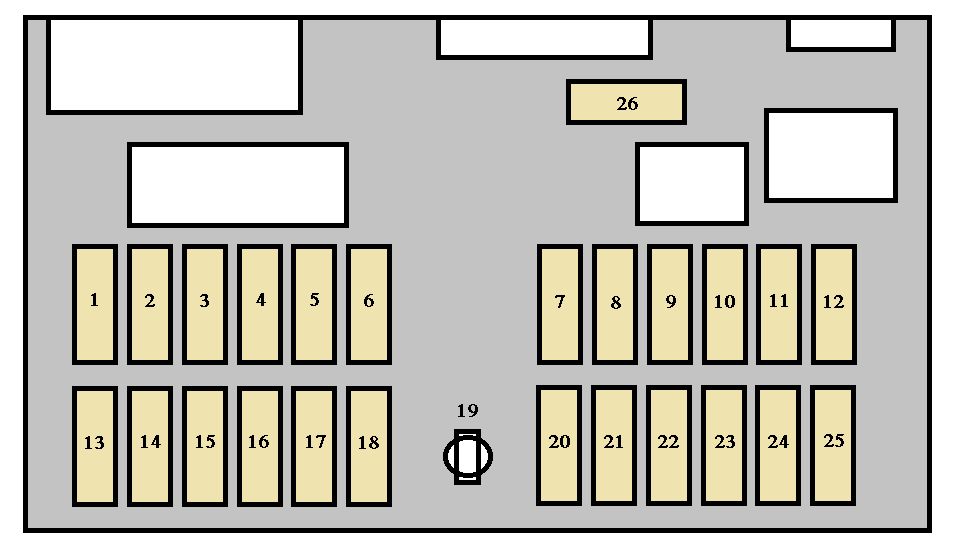
| Pozycja | Amperaż [A] | Chroniony obwód / funkcja |
|---|---|---|
| 1 | 10 | Rear fog lamp |
| 2 | 15 | Rear wiper |
| 3 | – | Unused |
| 4 | 15 | BSI power supply |
| 5 | 10 | Left brake lamp |
| 6 | – | Unused |
| 7 | 20 | Reading lights, lighter, glovebox light and electrochromatic mirror |
| 8 | – | Unused |
| 9 | 30 | Front power windows and first-row sunroof |
| 10 | 20 | Diagnostic and trailer connectors |
| 11 | 15 | Alarm, telematics, radio, displays, steering controls and DPF electronics |
| 12 | 10 | Right side lamps, plate lights, HVAC panel and cabin lighting |
| 13 | – | Unused |
| 14 | 30 | Central locking/deadlocking |
| 15 | 30 | Rear electric windows |
| 16 | 5 | Airbag ECU supplied through BSI |
| 17 | 15 | Right/third brake lamps and trailer stop lights |
| 18 | 10 | Diagnostic feed and brake/clutch switches |
| 19 | 40 | PARC configuration shunt, not an ordinary fuse |
| 20 | 10 | Radio power through BSI |
| 21 | – | Unused |
| 22 | 10 | Left side lamps and trailer position lights |
| 23 | 15 | Alarm siren and automatic gearbox ECU |
| 24 | 15 | Rear parking assistance |
| 25 | – | Unused |
| 26 | 40 | Heated rear screen |
Alternative dashboard carrier, usually 2006-2009
Some versions use a distinct F1-F30 electrical carrier. The lighter moves to F16 (20 A), the horn is F7 (20 A), front washer/wiper circuits use F24 (30 A), and the rear heater is F27 (30 A). F8 and F23 are configuration shunts; F10, F11 and F13 are shown as unused despite a nominal 30 A rating. No verified matching high-resolution F1-F30 drawing is available in the original source, so the diagram of the different 1-26 board is not mislabelled as this one.
| Pozycja | Amperaż [A] | Chroniony obwód / funkcja |
|---|---|---|
| F1 | 10 | Radio |
| F2 | 5 | Ignition switched controls, vehicle speed and dash lamps |
| F3 | 15 | Brake lamps and cruise control |
| F4 | 10 | Right rear and left front lamps, headlamp leveling |
| F5 | 10 | Climate controls, windows, fan and pressure sensor |
| F6 | 15 | Rear window heater and heated seats by equipment |
| F7 | 20 | Horn |
| F8 | Shunt | Electrical distribution shunt |
| F9 | 5 | Headlamp washer, side and plate lamps |
| F10 | 30 | Unused nominal 30A slot |
| F11 | 30 | Unused nominal 30A slot |
| F12 | 10 | ABS, reversing lights, diagnostic and automatic gearbox |
| F13 | 30 | Unused nominal 30A slot |
| F14 | 5 | BSI protection module |
| F15 | 30 | Main body power, central locking and lighting |
| F16 | 20 | Front lighter, permanent battery feed |
| F17 | 15 | Coolant temperature and cooling fan |
| F18 | 10 | Rear fog lamp |
| F19 | 10 | Dash lighting, radio and side lamps |
| F20 | 30 | Climate blower |
| F21 | 20 | Heated seats |
| F22 | 20 | Auxiliary consumers or unused |
| F23 | Shunt | PARC feed shunt for F14/F15/F25/F27 |
| F24 | 30 | Front windscreen washer and wiper |
| F25 | 10 | Air conditioning, courtesy lights and radio memory |
| F26 | 15 | Hazard warning flashers |
| F27 | 30 | Heated rear screen |
| F28 | 15 | Window controls and charge light |
| F29 | 30 | Power windows |
| F30 | 15 | Interior lamps, indicators, clock and power mirrors |
Dashboard from 2010-2014
The later driver’s handbook assigns dashboard 1 (15 A) to the rear wiper, 3 (5 A) to the airbag ECU, 8 (20 A) to the audio/display and sliding-door controller, 9 (30 A) to the lighter and 17 (40 A) to the rear glass heater. Position 2 is unused. The shared physical carrier sketch below locates numbered places, but the year-specific table gives their functions.
| Pozycja | Amperaż [A] | Chroniony obwód / funkcja |
|---|---|---|
| 1 | 15 | Rear window wiper |
| 2 | – | Unused |
| 3 | 5 | Airbag control unit |
| 4 | 10 | Steering angle, climate, clutch/brake, diagnostics, headlamp leveling, ESP, diesel additive and mirror |
| 5 | 30 | Power mirrors, passenger window and first-row sunroof |
| 6 | 30 | Front electric window supply |
| 7 | 5 | Courtesy, glovebox, vanity and entertainment lights |
| 8 | 20 | Audio, display, alarm, diesel additive, tyre pressure and sliding door controller |
| 9 | 30 | Front lighter and socket |
| 10 | 15 | Steering controls and trailer module |
| 11 | 15 | Diagnostics, ignition and four-speed automatic gearbox |
| 12 | 15 | Seat memory, powered passenger seat, airbags, parking, sliding doors, hands-free and six-speed automatic |
| 13 | 5 | Engine and trailer fuse modules |
| 14 | 15 | Rain sensing, automatic climate, instrument cluster, sunroofs and telematics |
| 15 | 30 | Passenger door locking |
| 16 | 30 | Central door lock and unlock |
| 17 | 40 | Heated rear glass |
Battery floor-box, earlier production
Early 807 battery holders protect the right/left powered sliding door motors at 1*/2* (40 A each), optional Hi-Fi amplifier 3* (30 A), and optional diesel heater 4* (30 A). Positions 29-31 are unused. The electric seats are 32/33 (25 A), second/third-row roof vents 35/34 (20 A), heated seats 37/36 (10 A), child safety lock 38 (15 A), and rear 12 V sockets 39/40 (20 A).
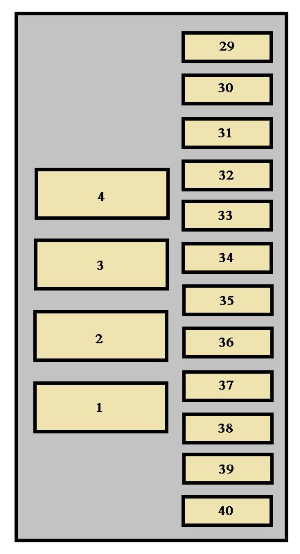
| Pozycja | Amperaż [A] | Chroniony obwód / funkcja |
|---|---|---|
| 1* | 40 | Right electric sliding side door, Maxi |
| 2* | 40 | Left electric sliding side door, Maxi |
| 3* | 30 | Hi-Fi amplifier, Maxi |
| 4* | 30 | Unused or diesel auxiliary heater, Maxi |
| 29 | – | Unused |
| 30 | – | Unused |
| 31 | – | Unused |
| 32 | 25 | Driver power seat |
| 33 | 25 | Passenger power seat |
| 34 | 20 | Third-row sunroof |
| 35 | 20 | Second-row sunroof |
| 36 | 10 | Passenger heated seat |
| 37 | 10 | Driver heated seat |
| 38 | 15 | Electric child safety lock |
| 39 | 20 | Third-row 12V socket |
| 40 | 20 | Second-row 12V socket |
Battery floor-box, 2010-2014
Manufacturer documentation from 2013 shows major changes: 3* is unused, 4* (40 A) protects the trailer fuse module, and 31 (5 A) is the main brake switch. Position 38 is a nominal 15 A place listed unused in the original 2013 Peugeot handbook, although some other-market catalogs associate it with xenon high beams. Do not populate it without checking the equipment. Sliding doors remain at 1*/2* and the rear sockets at 39/40.
| Pozycja | Amperaż [A] | Chroniony obwód / funkcja |
|---|---|---|
| 1* | 40 | Right electric sliding door, Maxi |
| 2* | 40 | Left electric sliding door, Maxi |
| 3* | – | Unused Maxi position |
| 4* | 40 | Trailer electrical carrier, Maxi |
| 29 | – | Unoccupied location, not assigned in 2013 handbook |
| 30 | – | Unoccupied location, not assigned in 2013 handbook |
| 31 | 5 | Main brake pedal switch |
| 32 | 25 | Driver seat memory |
| 33 | 25 | Passenger seat memory |
| 34 | 20 | Third-row sunroof |
| 35 | 20 | Second-row sunroof |
| 36 | 10 | Passenger heated seat |
| 37 | 10 | Driver heated seat |
| 38 | 15 | Nominal 15A position unused in official 2013 manual; other markets may assign xenon main-beam circuit |
| 39 | 20 | Third-row 12V accessory socket |
| 40 | 20 | Second-row 12V accessory socket |
Engine compartment, early F1-F18
On early cars engine 13 (15 A) protects the horn, 14 (10 A) the screenwash pumps, 17 (30 A) the front windscreen wipers, 9/10 (15 A) left/right dipped headlights and 11/12 (10 A) left/right main beams. Engine positions 1, 2, 8 and 15 have powertrain-specific injection, diesel heating and EGR functions; an unused F5 can instead power the diesel particulate control module.
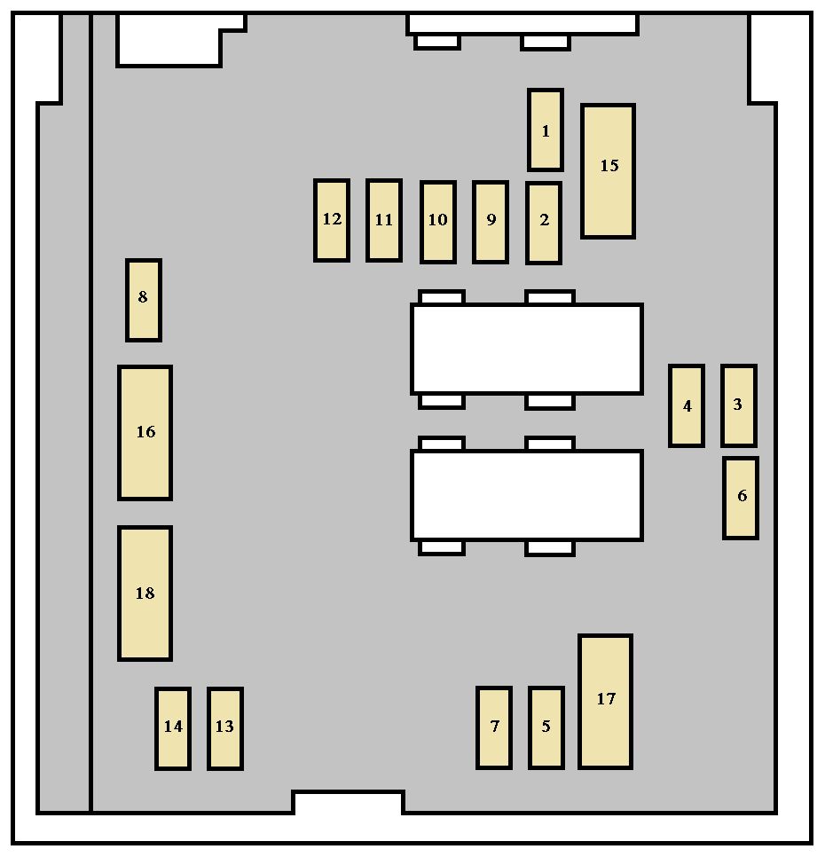
| Pozycja | Amperaż [A] | Chroniony obwód / funkcja |
|---|---|---|
| 1 | 10 | Manual gearbox reverse lamp, xenon, fan relay, coolant, diesel heating, speed or air sensor |
| 2 | 15 | Fuel pump, diesel EGR and turbo boost valves |
| 3 | 10 | ABS or ESP ECU |
| 4 | 10 | Engine fuse control after ignition |
| 5 | 10 | Unused or diesel DPF additive controls |
| 6 | 15 | Front fog lamps |
| 7 | 20 | Headlamp washers |
| 8 | 20 | Engine relay, diesel fan, fuel pressure and EGR control |
| 9 | 15 | Left dipped beam and leveling |
| 10 | 15 | Right dipped beam |
| 11 | 10 | Left high beam |
| 12 | 10 | Right high beam |
| 13 | 15 | Horn |
| 14 | 10 | Front and rear washer pumps |
| 15 | 30 | Petrol lambda, injectors, ignition, EVAP/EGR or diesel injection solenoid |
| 16 | 30 | Unused or petrol auxiliary air pump |
| 17 | 30 | Front wiper |
| 18 | 40 | Additional cabin blowers |
Early engine high-current Maxi fuses 1*-8*
Earlier engine Maxi positions 1* (50 A) and 6* (30 A) operate different cooling fan speeds, 2* (50 A) ABS/ESP, 3* (30 A) optional ESP or diesel heater, 4*/5* (60/70 A) BSI supplies, 7* (40 A) immobiliser, and 8* (50 A) additional ventilation. These are not ordinary owner-service blade fuses, and later Maxi positions have different consumers.
| Pozycja | Amperaż [A] | Chroniony obwód / funkcja |
|---|---|---|
| 1 | 50 | Radiator fan high speed |
| 2 | 50 | ABS or ESP main feed |
| 3 | 30 | Unused or ESP valves or diesel additional heating |
| 4 | 60 | BSI supply one |
| 5 | 70 | BSI supply two |
| 6 | 30 | Radiator fan low speed |
| 7 | 40 | Engine immobilizer |
| 8 | 50 | Auxiliary cabin and air conditioning blowers |
Engine compartment, later 2010-2014 F1-F15
The late board uses engine fuse 2 (15 A) for the horn, 3 (10 A) washer pumps, 4 (20 A) headlamp washing, 8 (20 A) starter, 11 (40 A) front A/C blower and 12 (30 A) front wipers. The 2013 Peugeot factory handbook says F9 (10 A) protects the main brake switch, though certain secondary sites describe an ECU function. F14 carries a nominal 30 A listing but is unused. The enlarged physical board sketch is provided only as a locator; use the year-specific list below.
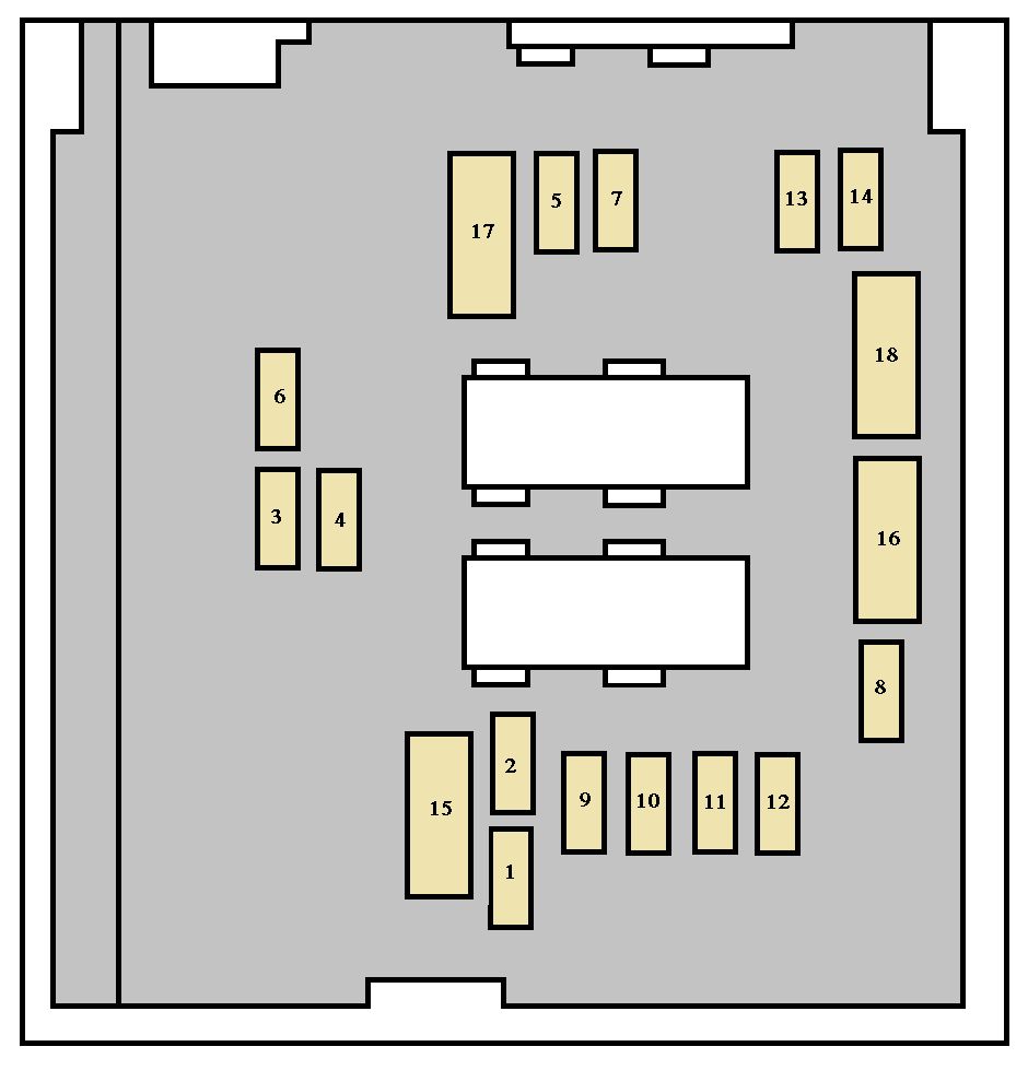
| Pozycja | Amperaż [A] | Chroniony obwód / funkcja |
|---|---|---|
| 1 | 20 | Engine ECU, fuel/air and radiator fans |
| 2 | 15 | Horn |
| 3 | 10 | Front/rear wash pump |
| 4 | 20 | Headlamp washer |
| 5 | 15 | Fuel supply |
| 6 | 10 | Steering, brake switch, automatic gearbox, air sensor and xenon leveling |
| 7 | 10 | ABS/ESP |
| 8 | 20 | Starter control |
| 9 | 10 | Main brake pedal switch in 2013 Peugeot handbook |
| 10 | 30 | Fuel, air and emissions controls |
| 11 | 40 | Front climate blower |
| 12 | 30 | Front windscreen wipers |
| 13 | 40 | Main BSI feed |
| 14 | 30 | Unused nominal 30A position |
| 15 | 30 | Child safety lock, unlock and deadlock |
Later 2010-2014 high-current Maxi layout
Later catalogs assign 1* (50 A) to A/C blowers, 2*/3* (50/30 A) to ABS/ESP, 4*/5* (60/70 A) to BSI main power and 6* (30 A) to supplementary diesel heating. Positions 7*/8* are listed unused despite nominal 40/50 A ratings. Peugeot’s owner manual reserves full Maxi and relay servicing for specialist workshops, so confirm a high-current link against the exact vehicle’s service documentation.
| Pozycja | Amperaż [A] | Chroniony obwód / funkcja |
|---|---|---|
| 1* | 50 | Air-conditioning blowers |
| 2* | 50 | ABS/ESP supply |
| 3* | 30 | Second ABS/ESP supply |
| 4* | 60 | BSI main supply 1 |
| 5* | 70 | BSI main supply 2 |
| 6* | 30 | Diesel auxiliary heater |
| 7* | 40 | Unused nominal 40A position |
| 8* | 50 | Unused nominal 50A position |
Practical Peugeot 807 fuse checks
Sliding door stops: Battery floor-box fuse 1* or 2* (40 A), then inspect the track, latch sensors, power wiring and motor controller. Rear accessory socket dead: Floor-box 40 (20 A) for row two, 39 (20 A) for row three. Front lighter: Dashboard 7 (early), F16 (mid), or 9 (later). A working third-row socket does not prove that the dashboard lighter fuse is good.
Rear wiper: Dashboard 2 (early) or 1 (later); confirm fitted carrier. Front wipers: Early engine 17 (30 A), mid dashboard F24 (30 A), later engine 12 (30 A). Horn: Early engine 13 (15 A), mid dashboard F7 (20 A), later engine 2 (15 A). Rear heater: Dashboard 26 (early), F27 (mid), 17 (later). Repeatedly blowing fuses indicate a circuit fault, not a reason to increase amperage.
Other Peugeot seven-seat fuse boxes
The Peugeot 5008 I (2009-2012) and Peugeot 5008 I (2014-2016) are later Peugeot family cars with different electrical layouts, but comparable rear power outlets and high-current body electronics.
References: Peugeot 807 official 2013 owner manual, pages 124-129; earlier Peugeot 807 handbooks for 2002-2009; catalog year variants checked against the manufacturer’s fuse tables.