
The first Peugeot 5008 I (2009-2012), chassis family T87, uses three physical electrical distribution locations: the lower dashboard, the under-bonnet fuse carrier beside the battery and a separate mini/midi and Maxi fuse group above the battery. Although the positions look similar throughout this period, important values change between the 2009-2010 and 2011-2012 handbooks. In particular the luggage 12 V outlet moves from F29 to F31, and the battery-mounted diesel pre-heating F9 changes from 70 A to 80 A in the later manufacturer’s specification. All 80 rows below, including quick-reference circuits and both F9 alternatives, remain explicitly distinguishable.
Location and access to the 5008 fuse boxes
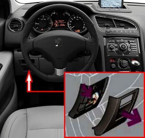
Passenger compartment: Switch off ignition and accessories. In a left-hand-drive 5008, the main carrier sits in the lower left dashboard. Open the service flap by pulling the fascia cover and release its fasteners without levering against adjacent electronics. On right-hand-drive vehicles, the trim and access can differ. The spare blades and extraction tweezer are usually clipped to the back of the cover. F1-F17 and the supplementary F29-F40 equipment positions are in the dashboard electrical area.
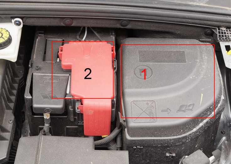
Engine compartment: Raise the bonnet and locate the sealed black fusebox alongside the battery on the left side. Release the retaining clips, check the actual F1-F21 fuse numbers, and refit the cover carefully to prevent water entry. Battery-mounted power links: A separate protected distribution carrier immediately above the battery houses F1-F12 mini/midi protection and MF1-MF8 Maxi fuses. Their high current means Peugeot specifies a qualified workshop for service.
Important 2009-2010 versus 2011-2012 differences
In the earlier 5008, supplementary F29 30 A protects the luggage-compartment power outlet and F31 15 A is the refrigerated storage-box circuit. Later instructions list F29 unused while F31 30 A feeds the boot 12 V socket. The battery F9 diesel-preheater rating is 70 A in the early 2009-2010 allocation and 80 A in the 2011-2012 owner’s manual; 30 A is used for the alternative 1.6 THP Valvetronic motor. Never replace a 70 A fuse with an 80 A fuse without confirming the actual vehicle’s wiring and factory specification.
Frequently checked Peugeot 5008 fuses
This nine-row index repeats actual circuits from the full tables. The engine F2 horn, engine F8 starter and engine F12 wipers are distinct from same-numbered dashboard positions.
| Pozycja | Amperaż [A] | Chroniony obwód / funkcja |
|---|---|---|
| F9 | 30 | Front lighter and front/rear 12 V accessory sockets, passenger compartment |
| F31 | 30 | Luggage-compartment 12 V socket in the 2011-2012 cabin allocation |
| F29 | 30 | Luggage-compartment 12 V socket in the 2009-2010 cabin allocation |
| F8 | 20 | Radio and multimedia, passenger compartment |
| F39 | 20 | Panoramic roof blind motor, cabin supplementary position |
| F17 | 40 | Heated rear window, passenger compartment |
| F2 | 15 | Horn, ENGINE compartment – not passenger F2 |
| F8 | 20 | Starter control, ENGINE compartment – not passenger F8 |
| F12 | 30 | Front windscreen wipers, ENGINE compartment |
Passenger-compartment main fuses F1-F17
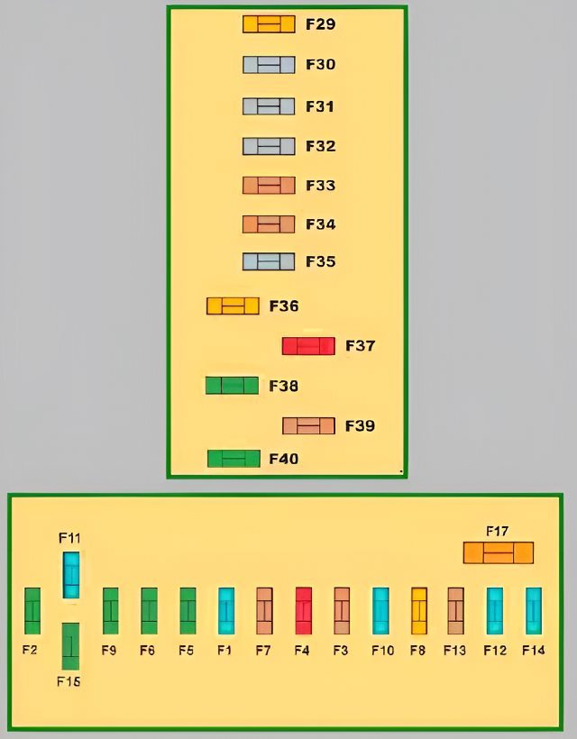
The basic dashboard board includes F1 15 A for the rear wiper, F5/F6 30 A for front and rear electric windows, F8 20 A for radio and multimedia, F9 30 A for the lighter and front/rear 12 V sockets and F17 40 A for rear window demisting. F2 is deliberately unused. The SH position is the PARC transport-mode shunt, not an ordinary fuse. The 2013-generation diagram reused below shows the same F1-F17 numbered architecture confirmed by both source tables, but production-specific fuse sizes always come from the printed chart.
| Pozycja | Amperaż [A] | Chroniony obwód / funkcja |
|---|---|---|
| F1 | 15 | Rear window wiper |
| F2 | – | Unused fuse socket in this electrical version |
| F3 | 5 | Airbag control unit |
| F4 | 10 | Electrochromatic rear-view mirror, air conditioning, switching/protection module and rear multimedia |
| F5 | 30 | Front one-touch electric windows |
| F6 | 30 | Rear one-touch electric windows |
| F7 | 5 | Interior courtesy and map lights, rear reading lamps, vanity mirrors, glovebox, centre armrest and boot 12 V socket relay |
| F8 | 20 | Radio, telephone, CD changer, multifunction display, tyre-pressure warning, alarm and telematics, where fitted |
| F9 | 30 | Front 12 V socket, cigarette lighter and rear 12 V accessory socket |
| F10 | 15 | Steering-wheel controls |
| F11 | 15 | Low-current ignition/anti-theft switch |
| F12 | 15 | Trailer detection, rain and light sensor, power supply for F32, F34 and F35 |
| F13 | 5 | Engine electrical carrier and airbag ECU supply |
| F14 | 15 | Instrument cluster, instrument display and F33 feed |
| F15 | 30 | Central locking and deadlocking |
| F17 | 40 | Heated rear window and F30 supply |
| SH | Shunt | PARC transport/parking configuration shunt, not an ordinary current-rated fuse |
Supplementary dashboard fuse group F29-F40
These are additional cabin electrical circuits, not part of the engine or battery box. F30 heats the exterior mirrors, F33 feeds the head-up display and Bluetooth, F35 relates to parking sensors and Hi-Fi permission, F37 protects an optional amplifier, F38 a powered driver seat and F39 the panoramic roof blind. F40 is unused. The F29 and F31 columns explicitly state the earlier and later year ranges in their functions.
| Pozycja | Amperaż [A] | Chroniony obwód / funkcja |
|---|---|---|
| F29 | 30 / – | 2009-2010: luggage-compartment 12 V outlet at 30 A; 2011 onward: unused (ratings shown in order 2009-2010 / 2011-2012) |
| F30 | 5 | Heated exterior door mirrors |
| F31 | 15 / 30 | 2009-2010: 15 A refrigerated storage/coolbox socket; 2011 onward: luggage-compartment 12 V outlet at 30 A (ratings shown in order 2009-2010 / 2011-2012) |
| F32 | 5 | Electronically controlled manual gearbox selector |
| F33 | 10 | Head-up display, Bluetooth and air conditioning |
| F34 | 5 | Seat-belt warning indicators |
| F35 | 10 | Parking sensors and authorisation of Hi-Fi amplifier |
| F36 | 10 | Trailer module and driver’s door control panel |
| F37 | 20 | Hi-Fi amplifier |
| F38 | 30 | Electric driver’s seat |
| F39 | 20 | Panoramic sunroof blind |
| F40 | – | Unused in the documented cabin carrier |
Engine compartment F1-F21
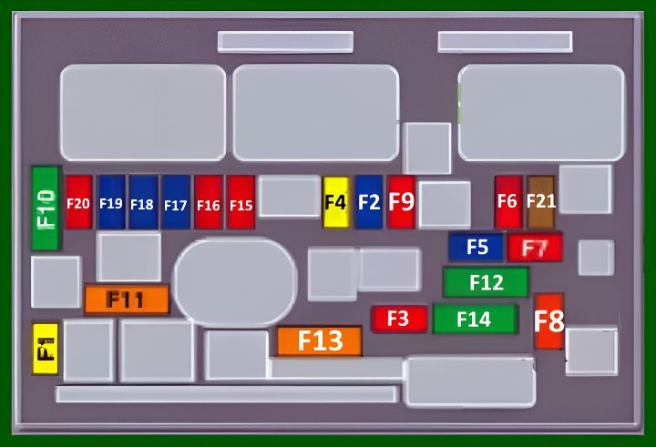
The main engine panel lists F2 15 A horn, F3 10 A screenwash, F4 10 A daytime running lights, F8 20 A starter control, F11 40 A cabin blower and F12 30 A front wipers. Petrol 1.6 THP circuits include turbo/EVAP solenoids, and 1.6/2.0 HDi versions include injection, EGR and diesel heating controls. The separate F15-F18 headlight fuses must not be mistaken for corresponding positions in the cabin.
| Pozycja | Amperaż [A] | Chroniony obwód / funkcja |
|---|---|---|
| F1 | 20 | Engine control ECU, injection pump and EGR valves on 2.0 HDi, plus injection equipment on fitted engines |
| F2 | 15 | Horn |
| F3 | 10 | Front and rear windscreen washer pumps |
| F4 | 10 | Daytime running lights |
| F5 | 15 | Fuel vapour canister purge, turbo pressure and wastegate control, oil vapour heater on THP or diesel heater depending on engine |
| F6 | 10 | Diagnostic connector, directional headlights, diesel particulate filter additive pump, Distance Alert, coolant level and mirror adjustment |
| F7 | 10 | Electric power-steering control, automatic gearbox and directional headlamp levelling |
| F8 | 20 | Starter motor control |
| F9 | 10 | Clutch and brake pedal switches |
| F10 | 30 | Engine ECU actuators: petrol ignition coils, solenoids, oxygen sensors, injectors, fuel pump and thermostat or diesel valves and heaters |
| F11 | 40 | Heater and air-conditioning blower motor |
| F12 | 30 | Front windscreen wiper motor, low and high speeds |
| F13 | 40 | BSI body electronics supply after ignition |
| F14 | 30 | Secondary air pump or engine-specific air system |
| F15 | 10 | Right-hand main-beam headlamp |
| F16 | 10 | Left-hand main-beam headlamp |
| F17 | 15 | Left-hand dipped-beam headlamp |
| F18 | 15 | Right-hand dipped-beam headlamp |
| F19 | 15 | Oil vapour heater, diesel turbo pressure regulation and engine coolant level sensor depending on engine |
| F20 | 10 | Electronically controlled thermostat, variable valve timing and turbo solenoids, engine coolant sensors |
| F21 | 5 | Radiator cooling fan relay, Valvetronic control, turbo cooling or airflow sensor according to powertrain |
Mini and midi fuses mounted above the battery
The battery carrier separately protects the brake switch, charging unit, ABS/ESP electronics, gearbox, power-steering pump, radiator fan and control modules. F7 80 A is the electric steering pump and F8 60 A is the radiator fan. F9 depends on both production period and powertrain: diesel preheating is 70 A in the 2009-2010 handbook and 80 A in the 2011-2012 handbook, while the 1.6 THP Valvetronic circuit is 30 A. Both factory variants appear as separate rows for clarity.
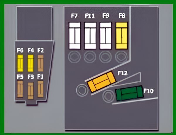
| Pozycja | Amperaż [A] | Chroniony obwód / funkcja |
|---|---|---|
| F1 | – | Unused position in the battery-mounted fuse carrier |
| F2 | 5 | Dual-function brake pedal switch |
| F3 | 5 | Battery charging unit |
| F4 | 25 | ABS/ESP hydraulic valve solenoids |
| F5 | 5 | ABS/ESP electronic controller |
| F6 | 15 | Automatic or piloted manual gearbox |
| F7 | 80 | Electric power steering pump main supply |
| F8 | 60 | Radiator cooling fan assembly |
| F9 | 70 / 30 | 2009-2010: 70 A for diesel preheating or 30 A for Valvetronic. The 2011-2012 Peugeot manuals revise the diesel rating to 80 A; see the additional row below |
| F9 | 80 / 30 | 2011-2012 handbook revision: 80 A diesel pre-heating or 30 A Valvetronic on 1.6 THP. Use the actual fitted rating, not another year’s 70 A fuse |
| F10 | 40 | ABS/ESP hydraulic electropump |
| F11 | 100 | Switching and protection unit |
| F12 | 30 | Electro-hydraulic pump of the electronically controlled manual gearbox |
High-current Maxi links MF1-MF8
The Maxi circuit group includes MF2 30 A for the trailer distribution, MF3 50 A for the cabin carrier, MF4/MF5 80 A for BSI power, MF6 30 A for the electric parking brake, MF7 30 A for heated seats and MF8 20 A for headlamp washers. MF1 is unused. These links are not standard user-serviceable blade fuses; a repeated failure requires tracing the protected load.
| Pozycja | Amperaż [A] | Chroniony obwód / funkcja |
|---|---|---|
| MF1 | – | Unused high-current position |
| MF2 | 30 | Trailer fuse box |
| MF3 | 50 | Passenger compartment fuse box main feed |
| MF4 | 80 | First BSI main high-current supply |
| MF5 | 80 | Second BSI main high-current supply |
| MF6 | 30 | Electric parking brake |
| MF7 | 30 | Heated front seats, when fitted |
| MF8 | 20 | Headlamp washer system |
Common electrical faults
Boot 12 V socket dead: Check F29 30 A on 2009-2010 cars or F31 30 A on 2011-2012 cars. If only one socket is affected, inspect the socket wiring and contacts. Front power outlet: Cabin F9 30 A. Panoramic blind stops: Supplementary F39 20 A, then the blind guides and electric motor.
Rear wiper failure: Cabin F1 15 A and the tailgate hinge harness. Front wipers not working: Engine F12 30 A and the linkage or motor. Horn silent: Engine F2 15 A. No cabin ventilation: Engine F11 40 A followed by the blower controller. Electric parking brake warning: MF6 30 A is the supply, but a sound fuse does not rule out actuator, wiring or module problems.
Related Peugeot generations
For the later but physically related configuration see Peugeot 5008 I (2013). The Peugeot 308 I T7 shares some underlying PSA electrical architecture, but position assignments and body-specific equipment must not be transferred between models.
Technical references: Peugeot 5008 2009 and 2012 manufacturer’s handbooks, including the cabin, engine and battery protection tables. Differences in F9 diesel preheating and F29/F31 luggage socket are production-specific.