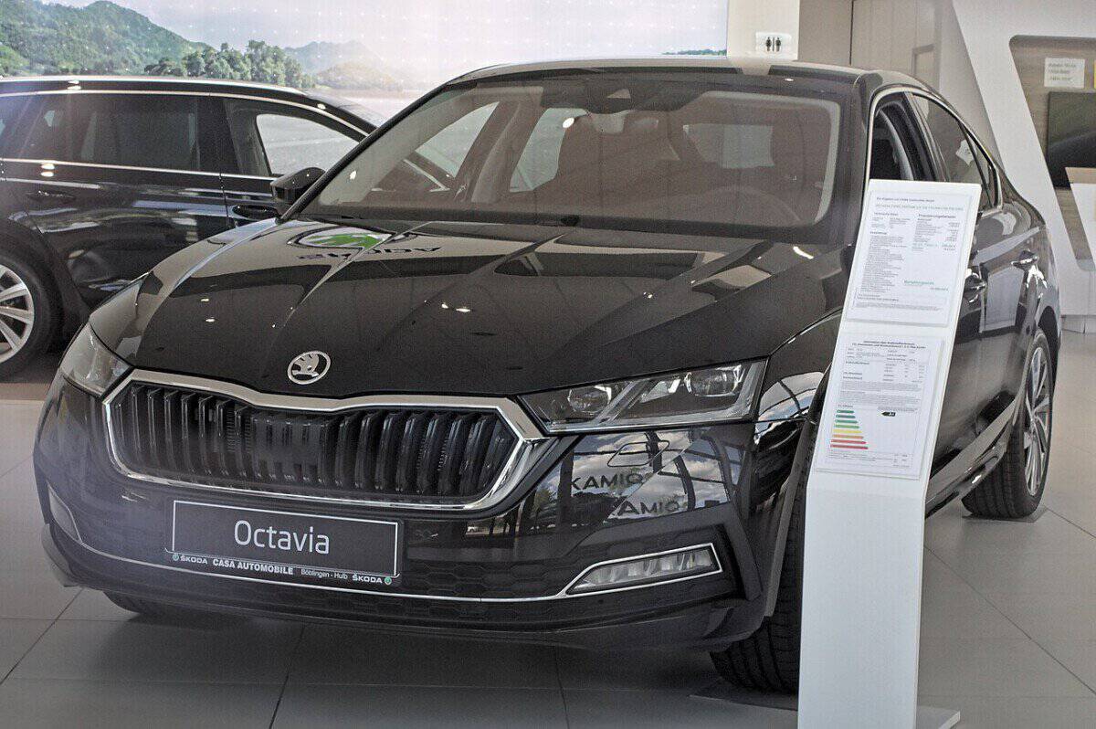
Skoda Octavia IV NX (2020-2026) is the fourth-generation liftback and estate. Its electrical system varies by engine, model year and trim, including petrol and diesel, mild-hybrid mHEV, plug-in hybrid Octavia iV and the 2024 facelift. The main fuse panels are SC beneath the driver’s dashboard and SB in the engine bay. Optional auxiliary cabin fuses and battery high-current SA fuses are also shown.
The tables below contain all 129 source entries across six tables: 67 SC fuses, six interior relays, 11 optional cabin positions, 32 SB fuses, eight engine-bay relays and five high-current SA fuses. These represent the archived configurations, not a universal guarantee for every 2020-2026 model. Especially for Octavia iV or 48 V mHEV, verify the correct vehicle-specific handbook before service. Never touch high-voltage hybrid hardware without appropriate training.
Where are the Octavia IV fuse boxes?
Passenger compartment: behind the lower driver’s dashboard storage panel on left-hand-drive cars; remove the access cover with ignition switched off. Engine bay: beneath a plastic protective cover near the 12 V battery on the left side. Other configurations have additional cabin fuses or main high-current protection next to the battery. Confirm the actual SC, SB and SA labels rather than matching the location alone.
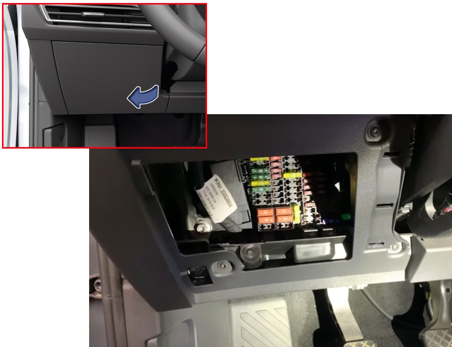
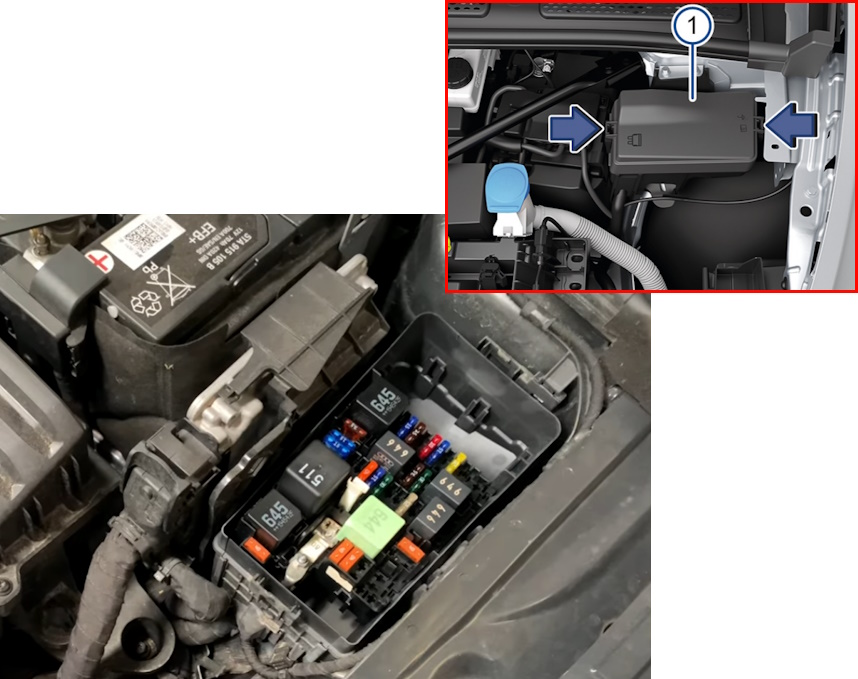
Octavia IV dashboard fuses SC1-SC67
The 67-position cabin chart includes body electronics, lighting, airbags, Haldex AWD, infotainment, KESSY, USB/Phonebox, heating and power sockets. 12 V accessory socket / cargo outlet: SC52 (20 A). Rear wiper: SC66 (15 A). Heated rear glass relay: SC67 (30 A). The optional USB supply at SC48 (7.5 A) is not present on all versions, and SC62 can supply another optional USB socket.
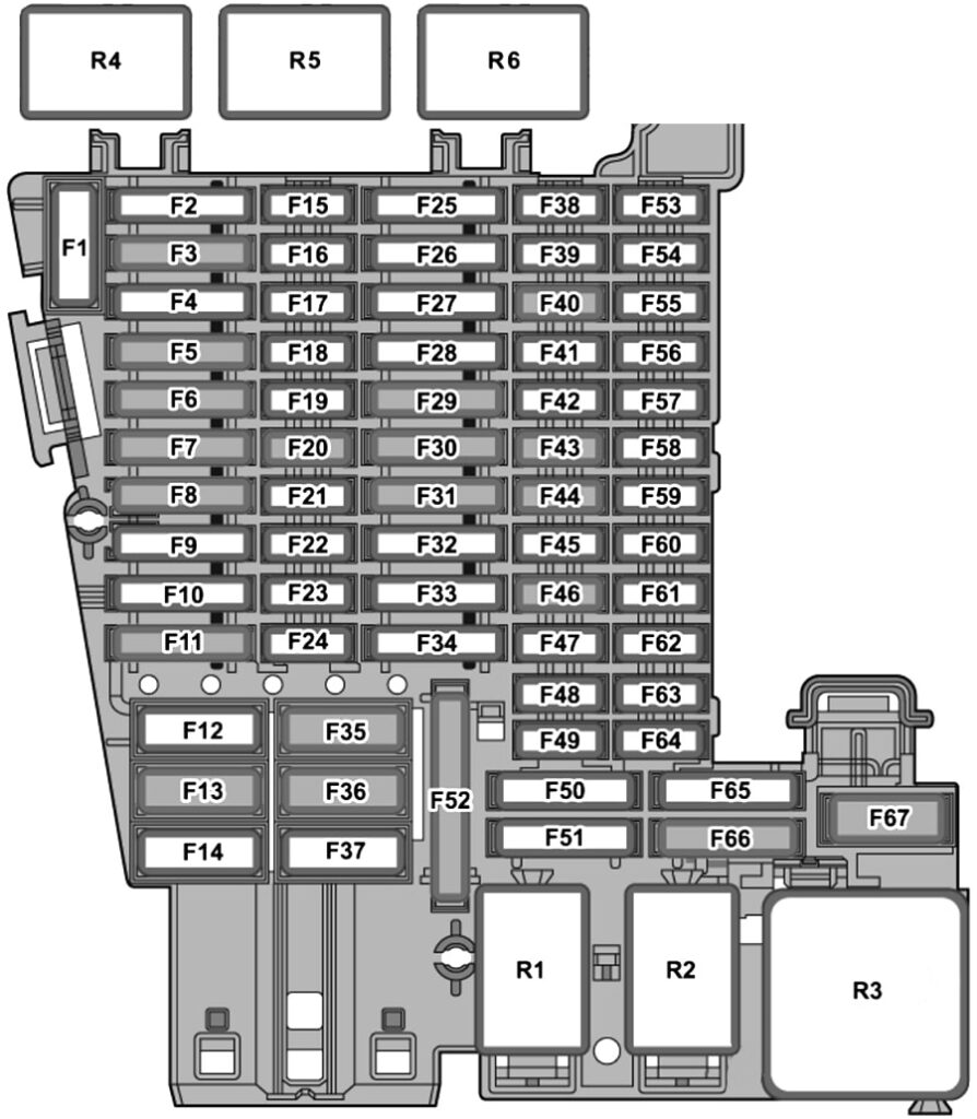
| Position | Rating [A] | Protected circuit / function |
|---|---|---|
| SC1 | – | Unused position |
| SC2 | – | Unused position |
| SC3 | 25 A | Trailer detection and towbar controller |
| SC4 | 20 A | SCR / AdBlue heating controller for diesel engines |
| SC5 | 25 A | Parking pawl / automatic transmission selector locking actuator |
| SC6 | 30 A | Vehicle electrical system control unit and interior lights |
| SC7 | 30 A | Heating and air-conditioning controller, heated seats |
| SC8 | 20 A | Power sliding and tilting roof controller |
| SC9 | 30 A | Door controllers and power windows, version dependent |
| SC10 | – | Unused position |
| SC11 | 15 A | Trailer controller |
| SC12 | 40 A | Vehicle electrical control module and left exterior lighting |
| SC13 | 40 A | Central locking and body electronics, windscreen washers on some versions |
| SC14 | 30 A | Audio amplifier / digital sound system |
| SC15 | – | Unused in standard configuration |
| SC16 | 7.5 A | Airbag control module |
| SC17 | 10 A | AdBlue dosing control relay |
| SC18 | 7.5 A | KESSY keyless access, electronic steering-column lock, door handles and anti-theft electronics |
| SC19 | 7.5 A | Instrument cluster, eCall emergency communication and telematics |
| SC20 | 7.5 A | Telephone / Phonebox, USB connectivity and communications functions according to equipment |
| SC21 | 7.5 A | Side Assist and lane-change electronics, exterior mirrors and tailgate camera or opening module depending on year |
| SC22 | – | Unassigned or optional equipment, model-year dependent |
| SC23 | – | Unassigned or optional equipment, model-year dependent |
| SC24 | 15 A | All-wheel-drive control module |
| SC25 | 25 A | Front seat-belt pretensioner, LHD/RHD side varies |
| SC26 | 30 A | Door electronics and power windows |
| SC27 | 25 A | Other front seat-belt pretensioner, LHD/RHD side varies |
| SC28 | – | Unused |
| SC29 | 15 A | Trailer controller |
| SC30 | 30 A | Infotainment electronics module |
| SC31 | 25 A | Trailer controller |
| SC32 | 25 A | Rear climate panel and heated rear bench |
| SC33 | – | Unused |
| SC34 | – | Optional 230 V socket and inverter |
| SC35 | 40 A | Vehicle electrical controller and right exterior lighting |
| SC36 | 40 A | Fresh-air and air-conditioning blower controller |
| SC37 | – | Optional electric tailgate |
| SC38 | – | Unused |
| SC39 | 10 A | Steering column electronics and optional heated steering wheel |
| SC40 | 7.5 A | Alarm siren and alarm system functions, year dependent |
| SC41 | 7.5 A | CAN data bus diagnostic gateway |
| SC42 | 7.5 A | Automatic gearbox selector mechanism and position display |
| SC43 | 10 A | Interior temperature sensor, parking heater, air conditioning and heated rear window relay |
| SC44 | 7.5 A | Parking brake, OBD port, roof module, alarm and rain/light sensors and lighting controls |
| SC45 | 7.5 A | Steering column switches |
| SC46 | 7.5 A | Infotainment and Head-up Display |
| SC47 | 10 A | Dynamic Chassis Control (DCC) adaptive suspension module |
| SC48 | 7.5 A | USB charger/socket in some versions; unused in other years |
| SC49 | – | Unused |
| SC50 | – | Unused |
| SC51 | – | Unused or version-specific equipment |
| SC52 | 20 A | 12 V power outlet, particularly luggage compartment or additional sockets |
| SC53 | – | Optional hands-free powered tailgate release |
| SC54 | – | Unused |
| SC55 | – | Unused |
| SC56 | – | Unused |
| SC57 | – | Unused |
| SC58 | 7.5 A | Driver-assistance camera, Park Assist, parking sensors and adaptive cruise radar |
| SC59 | 7.5 A | Parking brake, air conditioning, reversing gear sensor, interior mirror and air-quality sensor |
| SC60 | 7.5 A | Diagnostic connector |
| SC61 | 7.5 A | Starter relays, clutch pedal sensor and electric powertrain equipment on Octavia iV |
| SC62 | – | Additional USB socket, including optional connection near interior mirror |
| SC63 | – | Unused |
| SC64 | – | Unused |
| SC65 | 10 A | Engine or vehicle sound generator, equipment dependent |
| SC66 | 15 A | Rear window wiper motor |
| SC67 | 30 A | Heated rear window relay |
Passenger compartment relays R1-R6
These relays include the 12 V socket supply, terminal 15 switched ignition power, rear window heating and diesel AdBlue dosing. The last two relay positions may be unused.
| Relay | Function |
|---|---|
| R1 | Accessory power outlets relay |
| R2 | Terminal 15 switched ignition supply relay |
| R3 | Heated rear window relay |
| R4 | AdBlue dosing system relay on diesel versions |
| R5 | Unused or equipment dependent |
| R6 | Unused or equipment dependent |
Optional auxiliary cabin fuses A-P
Depending on equipment, a separate module protects driver/passenger powered seats, seat ventilation and special installations. A (15 A) supplies driver seat adjustments; D and E (15 A each) serve seat ventilation functions; and optional 40 A special-equipment fuses occupy K and L. Letters H-J and M-P are retained as source ranges, not incorrectly converted into additional numbered rows.
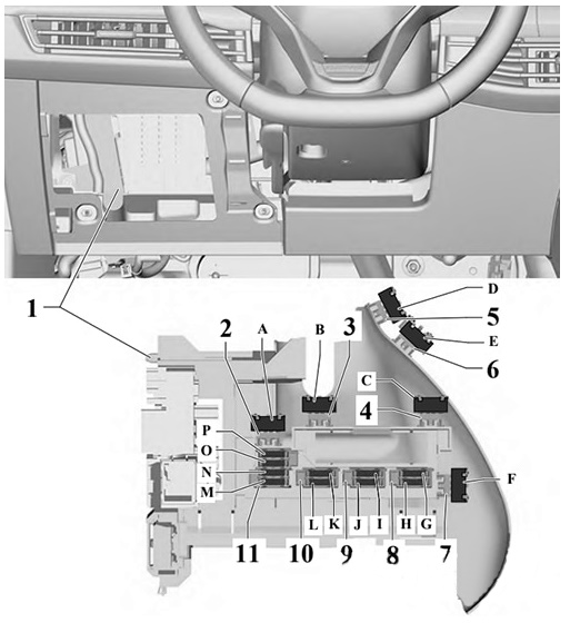
| Position | Rating [A] | Protected circuit / function |
|---|---|---|
| A | 15 A | Driver electric seat position-control module |
| B | – | Unused |
| C | – | Unused |
| D | 15 A | Driver seat backrest and cushion fans and seat-control panel |
| E | 15 A | Front passenger seat backrest and cushion fans and seat-control panel |
| F | – | Unused |
| G | 10 A | Special equipment and auxiliary connection points |
| H-J | – | Unused positions H through J |
| K | 40 A | Special equipment, 40 A |
| L | 40 A | Special equipment or auxiliary fuse holder, 40 A |
| M-P | – | Unused positions M through P |
Engine compartment fuse panel SB1-SB32
The SB unit protects steering, ABS/ESC, the ECM, the front wipers, horn, DSG control, starter, diesel auxiliary heating, fuel system and related sensors. SB1 (400 A) is a specialist high-current steering supply; SB10 (30 A) protects the front wiper motor; SB22 (30 A) is the starter; SB9 (15 A) the horn relay; and SB13 (25 A) plus SB15 (40 A) supply ABS/ESC. SB29 (15 or 20 A) is a fuel-pump controller depending on version.
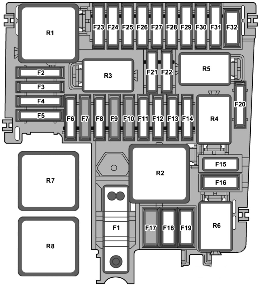
| Position | Rating [A] | Protected circuit / function |
|---|---|---|
| SB1 | 400 A | Power steering main high-current fuse; specialist replacement only |
| SB2 | 7.5 A | Main relay, terminal 30, ECM and ABS power, starter-generator functions on mHEV |
| SB3 | 7.5 / 20 A | Engine supply, different petrol and CNG systems; iV uses alternative functions |
| SB4 | 15 A | Left front headlamp |
| SB5 | 15 A | Right front headlamp |
| SB6 | – | Unused or optional |
| SB7 | 30 A | Auxiliary hydraulic gearbox oil pump |
| SB8 | 40 A | Brake servo |
| SB9 | 15 A | Horn relay |
| SB10 | 30 A | Front windscreen wiper motor |
| SB11 | – | Air-conditioning or powertrain-specific equipment |
| SB12 | 15 / 30 A | DSG mechatronics / automatic transmission control |
| SB13 | 25 A | ABS / ESC control module |
| SB14 | 20 A | Supplementary / parking heater controller |
| SB15 | 40 A | ABS / ESC control module high-current supply |
| SB16 | – | Unused or gearbox-specific equipment |
| SB17 | 40 A | Electric supplementary heater, mainly diesel |
| SB18 | 40 A | Second electric supplementary heater circuit, mainly diesel |
| SB19 | – | Unused |
| SB20 | 15 A | VAQ electronically controlled front differential lock, where fitted |
| SB21 | 7.5 A | Engine Control Module |
| SB22 | 30 A | Starter motor |
| SB23 | 15 A | Engine Control Module |
| SB24 | 7.5 / 10 A | Cooling fan, engine oil level/temperature, control valves, AdBlue, glow plugs and 48 V starter-generator as fitted |
| SB25 | 10 A | Powertrain components or CNG gas injectors |
| SB26 | 10 A | Engine management/cooling pumps and regulating valves |
| SB27 | 10 / 15 A | Particulate matter, lambda and NOx sensors |
| SB28 | 20 A | Ignition coils and engine electronics, engine-specific |
| SB29 | 15 / 20 A | Fuel pump controller |
| SB30 | – | Unused or engine-specific equipment |
| SB31 | – | Unused |
| SB32 | – | Heated front windscreen on some versions |
Engine compartment relays R1-R8
Eight source relay locations include the main engine relay, two starter relays, diesel electric-heater relays, glow-plug control, horn and CNG-specific valve controls.
| Relay | Function |
|---|---|
| R1 | Main relay |
| R2 | High-output heater relay on diesel models |
| R3 | Horn relay |
| R4 | Starter relay 1 |
| R5 | Starter relay 2 |
| R6 | Engine valves or CNG shut-off valve relay |
| R7 | Glow-plug controller / relay |
| R8 | Lower-output heater relay |
High-current battery fuses SA1-SA5
Separate battery distribution protection includes SA1 (150 A) for the engine fuse panel, SA2 (50 A) for the radiator cooling fan, and SA4 and SA5 (125 A each) for cabin power feeds. SA3 is unassigned or optional. Because these links carry high current, replacement should be carried out by trained service technicians.
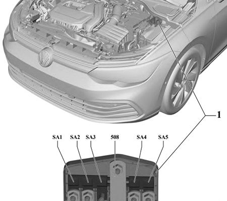
| Position | Rating [A] | Protected circuit / function |
|---|---|---|
| SA1 | 150 A | Engine compartment fuse box main feed |
| SA2 | 50 A | Radiator cooling fan |
| SA3 | – | Unused or optional equipment |
| SA4 | 125 A | Main passenger compartment fuse box feed |
| SA5 | 125 A | Second passenger compartment fuse box supply |
Octavia IV cigarette lighter, USB, fuel pump and wiper fuses
12 V socket, particularly in the boot: cabin SC52 (20 A). USB: optional cabin SC48 (7.5 A) and version-dependent SC62. Rear wiper: SC66 (15 A). Front wipers: engine SB10 (30 A). Starter: engine SB22 (30 A). Fuel pump: engine SB29 (15/20 A), depending on the installed fuel system. ABS: SB13 (25 A) and SB15 (40 A). Rear-window heater: cabin SC67 (30 A).
For the related but electrically different SUV, see the Skoda Kodiaq II (2024) fuse guide. For the first two generations, see the Skoda Octavia I / Tour and Skoda Octavia II. For the older generation, see Skoda Octavia III 5E (2013-2020). Also compare the Skoda Superb III as a separate vehicle – similar Volkswagen Group components do not imply identical fuse numbers.
Skoda Octavia IV NX 2020-2026 fuse box FAQ
Which fuse protects the cigarette lighter or luggage 12 V outlet?
SC52, rated 20 A in the documented layout, is primarily associated with the luggage 12 V outlet. Other 12 V sockets may have a different power supply depending on trim.
Where is the front windscreen wiper fuse?
Engine compartment SB10, rated 30 A in the source.
Does the 2024 facelift use the same diagram?
Not necessarily. Electrical functions and hybrid control systems can change; compare the exact vehicle’s manual and fuse-box cover.
Can I remove the 400 A SB1 fuse myself?
This is high-current power steering protection and should be serviced by trained personnel, not treated like a standard removable blade fuse.
What about plug-in hybrid Octavia iV?
Some SB/SC assignments are different. Do not attempt high-voltage service or replace protection without the specific hybrid service instructions.
Fit only the prescribed fuse type and current rating. A repeatedly blown fuse requires diagnosis, not an increased ampere value.