
Volvo S80 II (model year 2010) is the second-generation executive sedan. Its electrical protection is divided between a fuse box under the passenger glovebox, the upper/front/lower engine compartment distribution panel, and three numbered fuse modules in the left luggage-compartment area. Some S80 Executive versions also use a separate 5 A fuse for the analogue clock near the centre console.
This guide preserves 123 source entries in nine tables, with model-year 2010 ratings cross-checked against the Volvo S80 MY2010 owner’s manual, fuse section pages 242-250. The original illustrations are labelled as early second-generation S80 (2006 archives), so always confirm that the numbered layout matches the actual 2010 car and its lid. The diagram from another production year is not a reason to install a larger fuse.
Commonly checked S80 2010 fuses
Front and rear 12 V accessory sockets: F25 (15 A), engine compartment section B. Luggage compartment socket: F6 (15 A), rear module A. Fuel pump: cabin F22 (20 A). Radio/CD/ICM: cabin F6 (15 A). Front wipers: engine F9 (30 A). Horn: engine F29 (15 A). All are numbered within their respective fuse panels.
| Consumer | Fuse | Rating | Location |
|---|---|---|---|
| Front and rear 12 V accessory socket | F25 | 15 A | Engine compartment |
| Fuel pump | F22 | 20 A | Passenger glovebox |
| Radio, CD player, ICM display | F6 | 15 A | Passenger glovebox |
| Front wipers | F9 | 30 A | Engine compartment |
| Front windscreen washers | F14 | 15 A | Passenger glovebox |
| Horn | F29 | 15 A | Engine compartment |
| Cabin heater blower | F11 | 40 A | Engine compartment |
| Air-conditioning compressor | F32 | 15 A | Engine compartment |
| ABS pump | F13 | 40 A | Engine compartment |
| High-beam headlamps | F9 | 15 A | Passenger glovebox |
| Heated rear window | F7 | 30 A | Luggage compartment |
| Optional luggage compartment 12 V socket | F6 | 15 A | Luggage compartment |
Where are the Volvo S80 2010 fuse boxes?
The main cabin panel is behind the trim beneath the front passenger glovebox. The covered engine compartment box is near the battery, with upper, front and lower sections. The rear panel is behind the left luggage-compartment upholstery, with separate audio, door and power-seat/AWD modules. On right-hand-drive cars, interior access positions may differ.
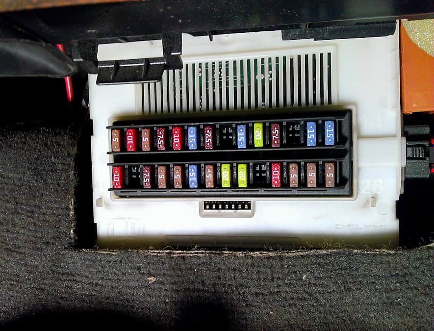
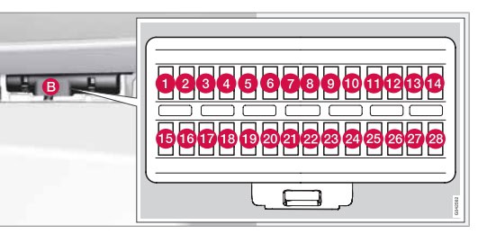
Passenger compartment: fuse positions F1-F28
The cabin box protects SRS, ABS/parking-brake electronics, rain sensor, infotainment, high beams, washer pump, fuel pump, central locking and starting controls. The key positions are F6 15 A for radio/CD, F14 15 A for the washer pump, F22 20 A for fuel pump, and F27 5 A for the engine START/STOP ignition button. This button must not be mistaken for automatic fuel-saving Stop/Start.
| Position | Rating [A] | Protected circuit |
|---|---|---|
| F1 | 5 | Rain sensor |
| F2 | 10 | SRS airbags |
| F3 | 5 | ABS / electric parking brake electronics |
| F4 | 7.5 | Accelerator pedal, PTC heater and optional heated seats |
| F5 | – | Unused |
| F6 | 15 | ICM display, CD and radio |
| F7 | 7.5 | Steering-wheel module |
| F8 | – | Unused |
| F9 | 15 | High-beam headlights |
| F10 | 20 | Optional electric sunroof |
| F11 | 7.5 | Reversing lights |
| F12 | – | Unused |
| F13 | 15 | Optional front fog lights |
| F14 | 15 | Windscreen washers |
| F15 | 10 | Optional adaptive cruise control |
| F16 | – | Unused |
| F17 | 7.5 | Roof lighting, driver door control and electric passenger seat |
| F18 | 5 | Information display |
| F19 | 5 | Power driver seat |
| F20 | 15 | Unused for MY2010 |
| F21 | 5 | Remote key and alarm sensors |
| F22 | 20 | Fuel pump |
| F23 | 20 | Electric steering column lock |
| F24 | 15 / – | Unused for MY2010 |
| F25 | 10 | Boot lid and fuel filler flap locking |
| F26 | 5 | Alarm siren and Electronic Climate Control |
| F27 | 5 | START/STOP ENGINE ignition button |
| F28 | 5 | Brake light switch |
Engine compartment fuse box – sections A, B and C
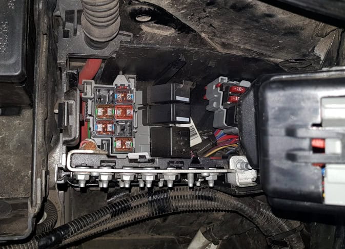
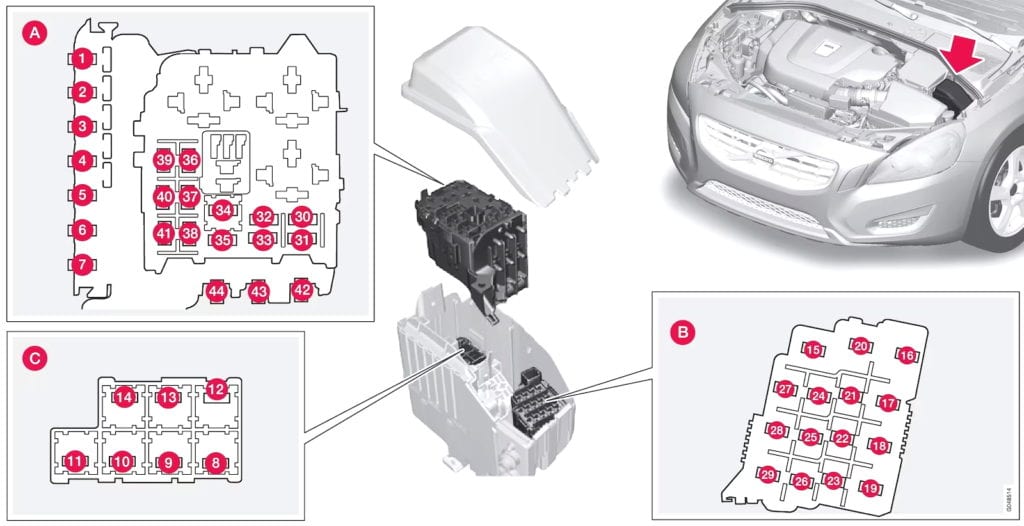
This covered unit has three separate physical sections. The following tables retain the original shared numbering but group it by position and electrical purpose. Volvo’s 2010 handbook distinguishes Midi, JCASE and MiniFuse types; high-current protection is intended for specialist replacement.
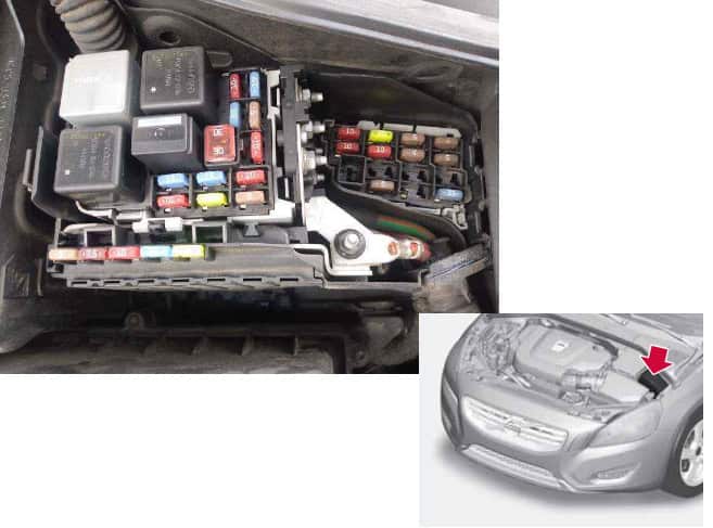
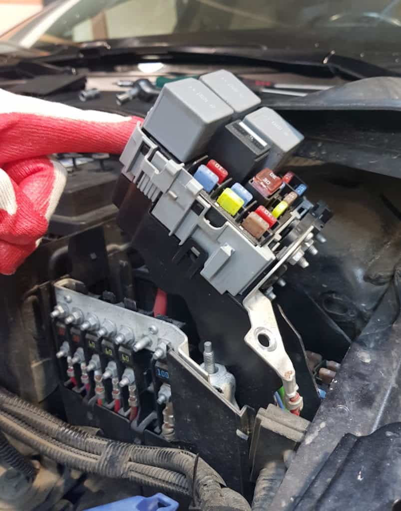
Engine section A: main supplies, ECM, engine sensors and cooling
For 2010, main fuse F5 is 50 A, not the 60 A sometimes shown in generic summaries. Diesel glow plug F42 is 60 A on four-cylinder or 70 A on five-cylinder engines. Cooling fan F44 is rated 60 A or 80 A depending on powertrain. F43 is not assigned in the documented MY2010 panel.
| Position | Rating [A] | Protected circuit |
|---|---|---|
| F1 | 50 | CEM primary KL30A power |
| F2 | 50 | CEM primary KL30B power |
| F3 | 60 | Rear Junction Box RJBA supply |
| F4 | 60 | Rear Junction Box RJBB supply |
| F5 | 50 | Rear Junction Box RJBD supply |
| F6 | – | Unused |
| F7 | 100 | Optional PTC electric auxiliary heater |
| F30 | 10 | Engine Control Module |
| F31 | 15 | Automatic gearbox module |
| F32 | 15 | Air-conditioning compressor clutch |
| F33 | 5 | Relay coils |
| F34 | 30 | Starter motor relay |
| F35 | 20 / 10 (diesel) | Ignition coils; diesel engine variants differ |
| F36 | 10 petrol / 15 diesel | Engine ECM and throttle, petrol or diesel |
| F37 | 15 / 10 diesel | Fuel injection and Mass Air Flow sensor |
| F38 | 10 | Engine valves and solenoids |
| F39 | 15 petrol / 10 other | EVAP, lambda sensor and fuel injection, engine dependent |
| F40 | 10 / 15 / 20 | V8 water pump or petrol/diesel crankcase and filter heating |
| F41 | – | Unused in 2010 reference |
| F42 | 60 (4-cyl diesel) / 70 (5-cyl diesel) | Diesel glow plugs: four-cylinder 60 A, five-cylinder 70 A |
| F43 | – | Unused in 2010 reference |
| F44 | 60 / 80 | Radiator cooling fan: 60 A or 80 A according to engine |
Engine section B: fuses F15-F29
Optional Xenon headlamp levelling F16 (10 A), CEM F17 (20 A), I5T vacuum pump F22 (20 A), headlamp washer F24 (15 A), accessory socket F25 (15 A), sunroof/roof console F26 (5 A) and horn F29 (15 A) are shown separately. Fuse F26 has been corrected from the original multi-year summary to the 2010 handbook rating.
| Position | Rating [A] | Protected circuit |
|---|---|---|
| F15 | – | Unused |
| F16 | 10 | Xenon / dual-Xenon headlamp levelling |
| F17 | 20 | CEM primary power |
| F18 | 5 | Adaptive cruise control radar, optional |
| F19 | 5 | Speed-dependent steering |
| F20 | 10 | ECM, transmission, SRS |
| F21 | 10 | Heated windscreen washer nozzles, optional |
| F22 | 20 | Vacuum pump, I5T engine |
| F23 | 5 | Lighting controls |
| F24 | 15 | Headlamp washers, optional |
| F25 | 15 | Front and rear 12 V outlets and optional rear-seat entertainment |
| F26 | 5 | Sunroof, roof console and electronic climate system |
| F27 | 5 | Engine-bay relay supply |
| F28 | 20 | Auxiliary lights, optional |
| F29 | 15 | Horn |
Engine section C: fuses F8-F14
Here the front wipers use F9 (30 A), optional parking heater F10 (25 A), climate blower F11 (40 A), ABS pump F13 (40 A), and ABS valves F14 (20 A). Positions F8 and F12 are unused in the official 2010 layout.
| Position | Rating [A] | Protected circuit |
|---|---|---|
| F8 | – | Unused for MY2010 |
| F9 | 30 | Front wipers |
| F10 | 25 | Optional parking heater |
| F11 | 40 | Climate system blower |
| F12 | – | Unused for MY2010 |
| F13 | 40 | ABS pump |
| F14 | 20 | ABS control valves |
Luggage compartment fuse boxes and relays
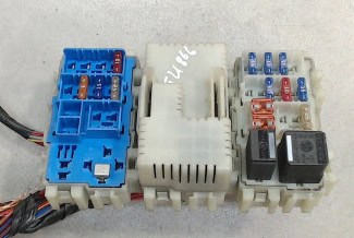
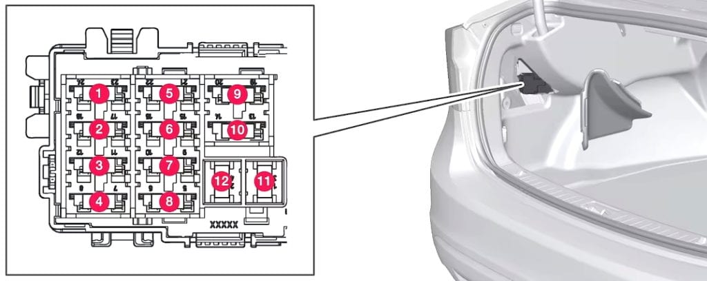
The rear panel contains three individually numbered groups, so an F6 in one module does not identify the same circuit in another. The original descriptions for factory audio, doors and accessory circuits have been preserved in English.
Module D: navigation, amplifier and telephone
| Position | Rating [A] | Protected circuit |
|---|---|---|
| F1 | 10 | Navigation display and reversing camera |
| F2 | – | Unused |
| F3 | – | Unused |
| F4 | 5 | Unused in 2010 reference |
| F5 | 25 | Factory audio amplifier |
| F6 | 15 | High Performance/Premium audio |
| F7 | 5 | Telephone and Bluetooth |
| F8-F12 | – | Unused positions F8 to F12 |
| R1 | – | Unused relay R1 |
| R2 | – | Unused relay R2 |
Module A: doors, heated glass, cargo 12 V outlet and trailer
The optional cargo socket/refrigerator uses module A F6 (15 A); heated rear glass F7 (30 A); and the main trailer electrical supply F11 (40 A).
| Position | Rating [A] | Protected circuit |
|---|---|---|
| F1 | 25 | Driver door electronics |
| F2 | 25 | Passenger door electronics |
| F3 | 25 | Left rear door electronics |
| F4 | 25 | Right rear door electronics |
| F5 | – | Unused |
| F6 | 15 | Boot 12 V socket and optional refrigerator |
| F7 | 30 | Heated rear window |
| F8 | 15 | Folding rear headrests, optional |
| F9 | 15 | Trailer electrical supply 2 |
| F10 | 25 | Driver electric seat |
| F11 | 40 | Trailer main electrical supply |
| F12 | – | Unused |
| R1 | – | Unused relay R1 |
| R2 | – | Heated rear-window relay R2 |
Module B: seats, AWD, Keyless and parking brake
The 2010 handbook lists F1 (7.5 A) for optional massage/armrest/refrigerator features, F6 (10 A) for AWD, F9 (25 A) for the passenger power seat and F11 (30 A) for the right parking brake. Generic multi-year values were corrected where the 2010 source differs.
| Position | Rating [A] | Protected circuit |
|---|---|---|
| F1 | 7.5 | Massage seats, armrest lighting and refrigerator, optional |
| F2 | 15 | Four-C active chassis module |
| F3 | 15 | Heated driver seat |
| F4 | 15 | Heated passenger seat |
| F5 | 15 | Heated right rear seat |
| F6 | 10 | AWD control module |
| F7 | 15 | Heated left rear seat |
| F8 | – | Unused on MY2010 reference |
| F9 | 25 | Power passenger seat |
| F10 | 20 | Keyless control |
| F11 | 30 | Left electric parking brake |
| F12 | – | Right electric parking brake |
| R1 | – | Unused relay R1 |
| R2 | – | Main ignition relay R2 |
S80 Executive additional clock fuse
Some Executive versions have a separate 5 A analogue clock fuse near the passenger-side centre console. It is not a general fourth fuse panel fitted to every S80.
| Position | Rating [A] | Protected circuit |
|---|---|---|
| 1 | 5 | Analogue clock, S80 Executive only |
Volvo S80 II 2010 fuse box FAQ
Which fuse protects the cigarette lighter?
F25 (15 A) in engine compartment section B. The optional cargo power outlet is rear module A F6 (15 A).
Where is the radio fuse?
The cabin holder under the glovebox, F6 (15 A) for the basic radio/CD and display circuit.
What fuse protects the windscreen wipers?
Engine fuse F9 (30 A). Washer pump protection is cabin F14 (15 A).
Which fuse protects the fuel pump?
Passenger fuse F22 (20 A).
Can these diagrams be used on every S80 from 2007-2016?
No. To compare the preceding production years, see the Volvo S80 II (2007) and S80 II (2008), alongside the 2009 guide. For the preceding production year, see the Volvo S80 II 2009 fuse diagram, noting especially the different F26 rating. Production changes, different engine families and optional equipment may alter the population and rating. Use the exact car’s fuse cover and manufacturer’s year-specific handbook.
For other P3 platform layouts see Volvo XC70 II / V70 III and Volvo S60 II (2011-2018). Fuse numbers are not directly interchangeable.
Source check: Volvo S80 owner’s manual MY2010, pages 242-250. Use original type and amperage; repeated fuse failures require circuit diagnosis.