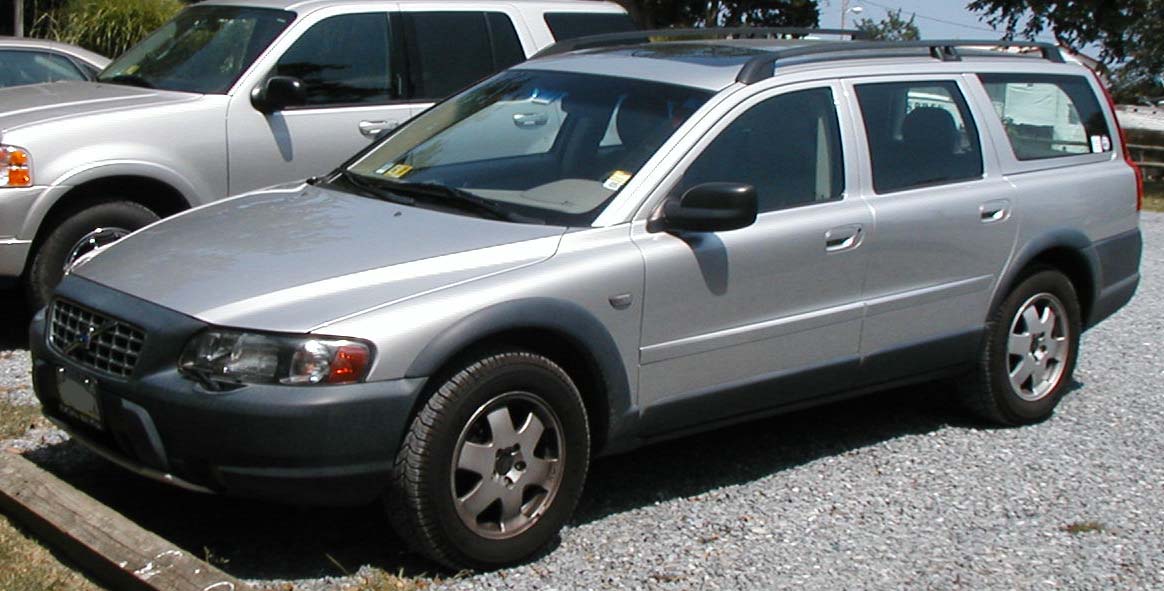
Volvo XC70 P2 (2003-2006) uses different fuse-box arrangements across its production years. The 2003 and 2004 cars have three fuse panels, while the 2005 and 2006 references have four, including an extra fuse box below the driver’s sound-insulation panel. Moreover, the 2005 engine-bay layout contains 24 positions, whereas the substantially revised 2006 layout has 21 positions.
Below are all 245 entries in nine tables from the Polish reference, with the eight original year-identified diagrams. The fuse numbers and ampere ratings are kept separate by model year. This is primarily based on USA XC70 owners’ documentation; European diesel equipment, parking heaters and options may differ. Check the actual car’s fuse cover and original handbook before replacing protection.
Volvo XC70 2003-2006 fuse box locations
2003-2004: under the bonnet, behind the cover at the left end of the dashboard, and behind the left cargo compartment side trim. Each fuse panel starts its own numbering at position 1.
2005-2006: under the bonnet, beneath the driver’s lower sound-insulation dashboard cover, in the separate left dashboard end panel, and behind the left luggage-compartment trim. The below-steering-wheel holder is a fourth fuse unit, not the same as the dashboard end panel.
Volvo XC70 2003-2004: three original fuse boxes
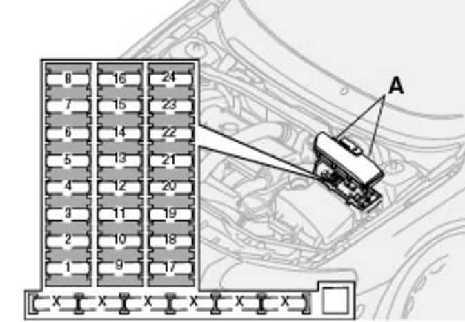
Engine compartment 1-24
Both years place the front wiper motor at engine fuse 13 (25 A), and the two ABS/DSTC circuits at 14 and 19 (30 A each). Engine position 3 (15 A) serves a vacuum pump in 2003 but is unused in the 2004 chart. The table therefore has separate amperage columns for each year.
| Position | 2003 rating [A] | 2004 rating [A] | Protected circuit |
|---|---|---|---|
| 1 | 25 | 25 | Accessory electrical equipment and optional consumer supply |
| 2 | 20 | 20 | Optional auxiliary headlamps |
| 3 | 15 | – | 2003 vacuum pump; slot unused in 2004 |
| 4 | 20 | 20 | Engine oxygen sensors |
| 5 | 10 | 10 | Crankcase breather heating and solenoid valves |
| 6 | 15 | 15 | Mass Air Flow (MAF) sensor, Engine Control Module (ECM) and injectors |
| 7 | 10 | 10 | Electronic throttle control module |
| 8 | 10 | 10 | A/C compressor control, accelerator-pedal sensor and electronics-box cooling fan |
| 9 | 15 | 15 | Horn |
| 10 | 10 | 10 | Rear tailgate wiper supply circuit |
| 11 | 20 | 20 | Ignition coils; the 2003 guide also identifies air conditioning |
| 12 | 5 | 5 | Brake pedal light switch |
| 13 | 25 | 25 | Front windscreen wiper motor |
| 14 | 30 | 30 | First ABS and STC/DSTC stability control circuit |
| 15 | – | – | Unassigned position |
| 16 | 15 | 15 | Front windscreen washer, and optional headlamp washer/wiper systems |
| 17 | 10 | 10 | Right dipped-beam headlamp |
| 18 | 10 | 10 | Left dipped-beam headlamp |
| 19 | 30 | 30 | Second ABS and STC/DSTC circuit |
| 20 | 15 | 15 | Left high-beam headlamp |
| 21 | 15 | 15 | Right high-beam headlamp |
| 22 | 25 | 25 | Starter circuit |
| 23 | 5 | 5 | Engine Control Module (ECM) |
| 24 | – | – | Unassigned position |
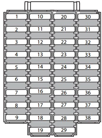
Left dashboard end 1-38
In 2004, position 5 (15 A) serves speed-sensitive steering and vacuum-pump control, while 10 and 11 (10 A each) protect daytime running lamps; these positions are unused in the 2003 list. For both years the cabin 12 V socket uses 13 (15 A), the OBD II-related diagnostic circuit 23 (5 A), the heater blower 26 (30 A) and the fuel pump 33 (15 A).
| Position | 2003 rating [A] | 2004 rating [A] | Protected circuit |
|---|---|---|---|
| 1 | 15 | 15 | Main dipped-beam headlamp feed |
| 2 | 20 | 20 | Main high-beam headlamp feed |
| 3 | 30 | 30 | Driver power seat |
| 4 | 30 | 30 | Passenger power seat |
| 5 | – | 15 | Unused in 2003; 2004 speed-sensitive steering and vacuum pump |
| 6 | – | – | Unused position |
| 7 | 15 | 15 | Left front seat heating, if fitted |
| 8 | 15 | 15 | Right front seat heating, if fitted |
| 9 | 5 | 5 | ABS/STC/DSTC electronic control |
| 10 | – | 10 | Unused in 2003; 2004 daytime running lamps (DRL) |
| 11 | – | 10 | Unused in 2003; 2004 daytime running lamps (DRL), second circuit |
| 12 | 15 | 15 | Headlamp wipers on equipped models |
| 13 | 15 | 15 | 12 V passenger-compartment accessory socket |
| 14 | 5 | 5 | Additional electric passenger-seat supply |
| 15 | 5 | 5 | Factory audio and Volvo Navigation System (VNS) |
| 16 | 20 | 20 | Factory audio system |
| 17 | 30 | 30 | Factory audio amplifier |
| 18 | 15 | 15 | Front fog lamps on equipped vehicles |
| 19 | 10 | 10 | Volvo Navigation System (VNS) display |
| 20 | – | – | Unused position |
| 21 | 10 | 10 | Automatic transmission, shiftlock and D2 circuit |
| 22 | 20 | 20 | Direction indicators |
| 23 | 5 | 5 | Light switch, climate control, OBD II diagnostic connector and steering column stalk modules |
| 24 | 10 | 10 | Power supply relay D1 for climate controls, driver seat and driver information display |
| 25 | 10 | 10 | Ignition switch, starter relay, Supplemental Restraint System (SRS) and engine controller |
| 26 | 30 | 30 | Heating and air-conditioning blower motor |
| 27 | – | – | Unused position |
| 28 | 10 | 10 | Interior lighting control module |
| 29 | – | – | Unused position |
| 30 | 7.5 | 7.5 | Left front and rear position lamps |
| 31 | 7.5 | 7.5 | Right position lamps and number-plate lighting |
| 32 | 10 | 10 | Central Electronic Module (CEM), mirror, glovebox and interior lights |
| 33 | 15 | 15 | Fuel pump |
| 34 | 15 | 15 | Electric sunroof, if fitted |
| 35 | 25 | 25 | Left door locking, power window and mirror module |
| 36 | 25 | 25 | Right door locking, power window and mirror module |
| 37 | 30 | 30 | Rear power windows and child-proof door locking, if fitted |
| 38 | 5 | 5 | Alarm siren; removing the fuse may trigger the alarm |
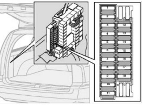
Left rear luggage compartment 1-18
The cargo-area power socket is protected by 7 (15 A), the rear wiper by 12 (15 A), and the All-Wheel Drive (AWD) controller by 17 (7.5 A). Trailer wiring has separate permanent and ignition-controlled circuits.
| Position | 2003 rating [A] | 2004 rating [A] | Protected circuit |
|---|---|---|---|
| 1 | 10 | 10 | Rear Electronic Module (REM) and luggage compartment lighting |
| 2 | 10 | 10 | Rear fog lamp |
| 3 | 15 | 15 | Brake lights |
| 4 | 10 | 10 | Reversing lamps |
| 5 | 5 | 5 | Heated rear window control and accessory relay 15I |
| 6 | 10 | 10 | Tailgate latch release |
| 7 | 15 | 15 | Luggage-compartment 12 V socket if installed |
| 8 | 20 | 20 | Central locking for rear doors and fuel filler flap |
| 9 | 15 | 15 | Permanent trailer electrical supply, circuit 30 |
| 10 | 10 | 10 | CD changer and Volvo Navigation System (VNS) |
| 11 | 15 | 15 | Accessory Electronic Module (AEM) |
| 12 | 15 | 15 | Additional rear tailgate wiper circuit |
| 13 | 15 | 15 | Optional luggage-compartment subwoofer |
| 14 | 7.5 | 7.5 | Additional brake-light control |
| 15 | 20 | 20 | Trailer towbar ignition-controlled supply, circuit 15I |
| 16 | – | – | Unused position |
| 17 | 7.5 | 7.5 | All-wheel-drive (AWD) controller power supply; does not prove the AWD pump is functioning |
| 18 | – | – | Unused position |
Volvo XC70 2005: engine compartment fuses 1-24
The 2005 main panel is not identical to 2003-2004. The source specifies front windscreen wipers at 13 (25 A), ABS at 14 and 19 (30 A each), fuel pump at 21 (15 A), starter at 22 (35 A) and engine control at 23 (10 A). Engine position 15 is a 35 A headlamp washer circuit in the documented 2005 equipment.
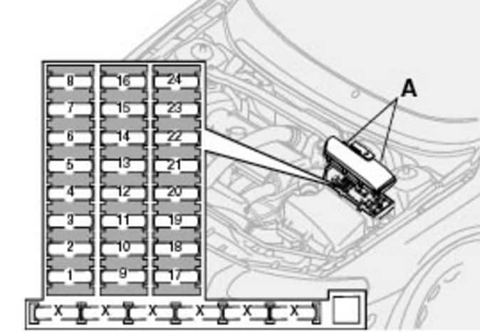
| Position | Rating [A] | Protected circuit |
|---|---|---|
| 1 | – | Unused in the standard 2005 Volvo XC70 owner’s layout |
| 2 | 20 | Optional auxiliary driving lights |
| 3 | 10 | Electronic throttle module on selected naturally aspirated engines |
| 4 | 20 | Exhaust oxygen sensors |
| 5 | 10 | Crankcase breather heater, solenoids and fuel-tank leak-detection system |
| 6 | 15 | MAF airflow sensor, ECM and fuel injectors |
| 7 | – | Unused in the standard 2005 Volvo XC70 owner’s layout |
| 8 | 10 | Air-conditioning control, accelerator pedal sensor and E-box fan |
| 9 | – | Unused in the standard 2005 Volvo XC70 owner’s layout |
| 10 | – | Unused in the standard 2005 Volvo XC70 owner’s layout |
| 11 | 20 | Ignition coils |
| 12 | – | Unused in the standard 2005 Volvo XC70 owner’s layout |
| 13 | 25 | Front windscreen wipers |
| 14 | 30 | First ABS circuit |
| 15 | 35 | Headlamp washers on equipped models |
| 16 | – | Unused in the standard 2005 Volvo XC70 owner’s layout |
| 17 | 20 | Left dipped-beam headlamp |
| 18 | 15 | Front position lamps |
| 19 | 30 | Second ABS circuit |
| 20 | 20 | Right dipped-beam headlamp |
| 21 | 15 | Fuel pump |
| 22 | 35 | Starter |
| 23 | 10 | ECM and its engine-management relay |
| 24 | – | Unused in the standard 2005 Volvo XC70 owner’s layout |
Volvo XC70 2006: revised 21-position engine bay box
For 2006, the factory USA guide lists 21 positions rather than 24 in the under-bonnet holder. The separate ABS circuits move to 1 and 2 (30 A each), the starter relay is at 6 (35 A), front wipers at 7 (25 A), fuel pump at 9 (15 A) and ECM at 19 (5 A). The 2005 under-bonnet drawing must not be substituted for this 2006 unit.
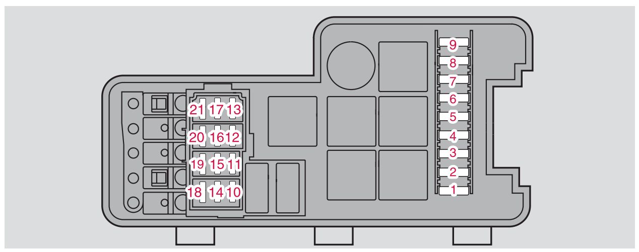
| Position | Rating [A] | Protected circuit |
|---|---|---|
| 1 | 30 | First ABS circuit |
| 2 | 30 | Second ABS circuit |
| 3 | – | Unused position |
| 4 | – | Unused position |
| 5 | 20 | Optional auxiliary headlamps |
| 6 | 35 | Starter relay |
| 7 | 25 | Front windscreen wipers |
| 8 | – | Unused in the USA manual; European diesel configurations may differ |
| 9 | 15 | Fuel pump |
| 10 | 20 | Ignition coils and ECM |
| 11 | 10 | Accelerator pedal sensor, A/C clutch and ECU cooling fan |
| 12 | 15 | ECM, fuel injectors and MAF airflow sensor |
| 13 | 10 | Electronic throttle control module |
| 14 | 20 | Heated oxygen sensor |
| 15 | 10 | Crankcase ventilation heating and solenoid valves |
| 16 | 20 | Left dipped-beam headlamp |
| 17 | 20 | Right dipped-beam headlamp |
| 18 | – | Unused position |
| 19 | 5 | ECM and engine-management relay supply |
| 20 | 15 | Position and parking lights |
| 21 | – | Unused position |
Volvo XC70 2005-2006: three other fuse boxes
Additional panel beneath the driver’s sound insulation 1-36
In this holder, position 11 (15 A) feeds interior 12 V sockets, 3 (15 A) the horn, 15 (5 A) ABS electronics, and 1 and 2 (15 A each) the heated front seats. Some circuits are identified for V70 R equipment and should not be assumed to exist in every XC70.
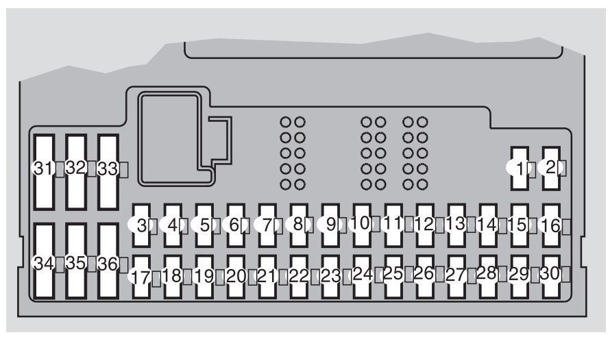
| Position | Rating [A] | Protected circuit |
|---|---|---|
| 1 | 15 | Front passenger heated seat |
| 2 | 15 | Driver heated seat |
| 3 | 15 | Horn |
| 4 | – | Unused in standard XC70 2005 reference |
| 5 | – | Unused in standard XC70 2005 reference |
| 6 | – | Unused in standard XC70 2005 reference |
| 7 | – | Unused in standard XC70 2005 reference |
| 8 | 5 | Alarm siren |
| 9 | 5 | Brake-light switch supply |
| 10 | 10 | Instrument cluster, automatic climate system and passenger occupancy sensor in selected markets |
| 11 | 15 | Front and rear passenger compartment 12 V power sockets |
| 12 | – | Unused in standard XC70 2005 reference |
| 13 | – | Unused in standard XC70 2005 reference |
| 14 | 15 | Headlamp wipers on V70 R equipment; not fitted to every XC70 |
| 15 | 5 | ABS/STC/DSTC control electronics |
| 16 | 10 | Power steering and active Bi-Xenon headlamp controls |
| 17 | 7.5 | Left front fog lamp |
| 18 | 7.5 | Right front fog lamp |
| 19 | – | Unused in standard XC70 2005 reference |
| 20 | – | Unused in standard XC70 2005 reference |
| 21 | 10 | Transmission controller and M66 reverse-gear lockout |
| 22 | 10 | Left high-beam headlamp |
| 23 | 10 | Right high-beam headlamp |
| 24 | – | Unused in standard XC70 2005 reference |
| 25 | – | Unused in standard XC70 2005 reference |
| 26 | – | Unused in standard XC70 2005 reference |
| 27 | – | Unused in standard XC70 2005 reference |
| 28 | 5 | Passenger seat electrical supply and audio system |
| 29 | – | Unused in standard XC70 2005 reference |
| 30 | – | Unused in standard XC70 2005 reference |
| 31 | – | Unused in standard XC70 2005 reference |
| 32 | – | Unused in standard XC70 2005 reference |
| 33 | 20 | Vacuum pump |
| 34 | 15 | Headlamp washer pump on V70 R variant |
| 35 | – | Unused in standard XC70 2005 reference |
| 36 | – | Unused in standard XC70 2005 reference |
Dashboard left end panel 1-38
The separate end-of-dashboard holder includes 3 (30 A) for the climate blower, 9 (5 A) for OBD II, 10 (20 A) for the factory audio head unit and 11 (30 A) for the amplifier. Many slots are unused in the base owners’ guide; their numbering remains visible below.
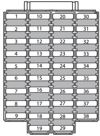
| Position | Rating [A] | Protected circuit |
|---|---|---|
| 1 | 25 | Electric driver seat |
| 2 | 25 | Electric passenger seat |
| 3 | 30 | Heating and air-conditioning blower motor |
| 4 | 25 | Right front door control module |
| 5 | 25 | Left front door control module |
| 6 | 10 | Upper cabin light and Upper Electronic Module (UEM) |
| 7 | 15 | Electric sunroof |
| 8 | 7.5 | Ignition switch, SRS controller, ECM and immobiliser |
| 9 | 5 | OBD II diagnostic connector, headlamp switch and steering angle sensor |
| 10 | 20 | Factory audio system |
| 11 | 30 | Factory audio amplifier |
| 12 | 10 | RTI navigation display |
| 13 | – | Unused in standard XC70 2005 reference |
| 14 | – | Unused in standard XC70 2005 reference |
| 15 | – | Unused in standard XC70 2005 reference |
| 16 | – | Unused in standard XC70 2005 reference |
| 17 | – | Unused in standard XC70 2005 reference |
| 18 | – | Unused in standard XC70 2005 reference |
| 19 | – | Unused in standard XC70 2005 reference |
| 20 | – | Unused in standard XC70 2005 reference |
| 21 | – | Unused in standard XC70 2005 reference |
| 22 | – | Unused in standard XC70 2005 reference |
| 23 | – | Unused in standard XC70 2005 reference |
| 24 | – | Unused in standard XC70 2005 reference |
| 25 | – | Unused in standard XC70 2005 reference |
| 26 | – | Unused in standard XC70 2005 reference |
| 27 | – | Unused in standard XC70 2005 reference |
| 28 | – | Unused in standard XC70 2005 reference |
| 29 | – | Unused in standard XC70 2005 reference |
| 30 | – | Unused in standard XC70 2005 reference |
| 31 | – | Unused in standard XC70 2005 reference |
| 32 | – | Unused in standard XC70 2005 reference |
| 33 | – | Unused in standard XC70 2005 reference |
| 34 | – | Unused in standard XC70 2005 reference |
| 35 | – | Unused in standard XC70 2005 reference |
| 36 | – | Unused in standard XC70 2005 reference |
| 37 | – | Unused in standard XC70 2005 reference |
| 38 | – | Unused in standard XC70 2005 reference |
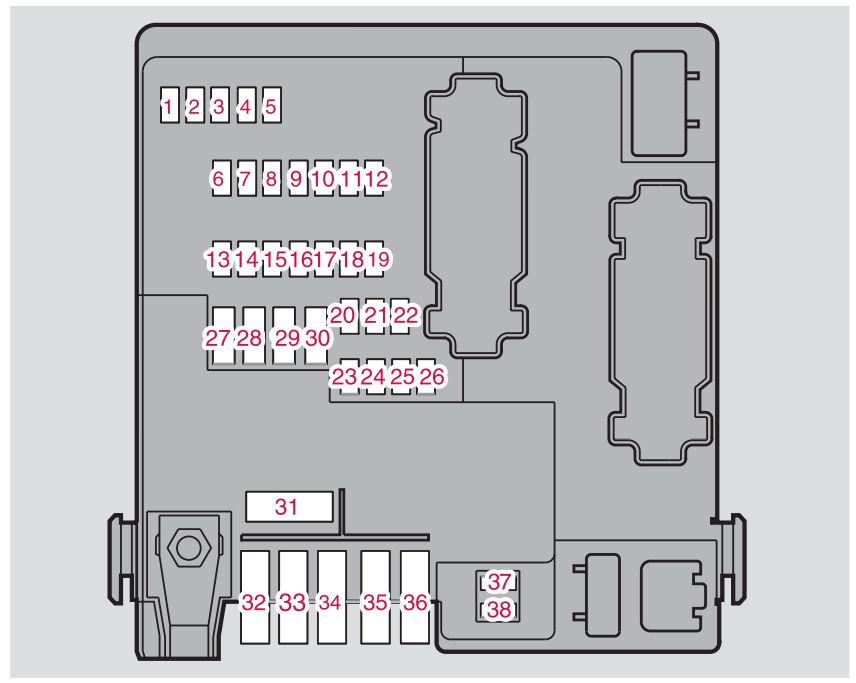
Left luggage compartment fuse panel 1-38
This panel supplies the rear 12 V socket through 8 (15 A), rear tailgate wiper through 19 (15 A), AWD controller through 23 (7.5 A) and the two heated rear-window circuits through 37 and 38 (20 A each). Importantly, trailer right-side lighting position 30 is 25 A, not 40 A as incorrectly shown on some web diagrams.
| Position | Rating [A] | Protected circuit |
|---|---|---|
| 1 | 10 | Reversing lights |
| 2 | 20 | Position, fog, tailgate, registration plate and brake lighting |
| 3 | 15 | Accessory Electronic Module (AEM) |
| 4 | – | Unused in standard XC70 2005 reference |
| 5 | 10 | Rear Electronic Module (REM) |
| 6 | 7.5 | Factory CD changer and RTI navigation |
| 7 | 15 | Trailer permanent power supply, circuit 30 |
| 8 | 15 | Luggage compartment 12 V power socket |
| 9 | 20 | Right rear power window and child safety window lock |
| 10 | 20 | Left rear power window and child safety window lock |
| 11 | – | Unused in standard XC70 2005 reference |
| 12 | – | Unused in standard XC70 2005 reference |
| 13 | – | Unused in standard XC70 2005 reference |
| 14 | 15 | Optional luggage-compartment subwoofer |
| 15 | – | Unused in standard XC70 2005 reference |
| 16 | – | Unused in standard XC70 2005 reference |
| 17 | 5 | Audio system accessory supply |
| 18 | – | Unused in standard XC70 2005 reference |
| 19 | 15 | Rear tailgate windscreen wiper |
| 20 | 20 | Trailer ignition-controlled power supply, circuit 15 |
| 21 | – | Unused in standard XC70 2005 reference |
| 22 | – | Unused in standard XC70 2005 reference |
| 23 | 7.5 | All-wheel-drive (AWD) module |
| 24 | 15 | Optional Four-C active suspension |
| 25 | – | Unused in standard XC70 2005 reference |
| 26 | 5 | Optional parking sensors |
| 27 | 30 | Main supply for trailer, Four-C, parking assistance and AWD circuits |
| 28 | 15 | Central locking |
| 29 | 25 | Left trailer lighting |
| 30 | 25 | Right trailer lighting, 25 A as documented rather than the incorrect 40 A in some diagrams |
| 31 | 40 | Main protection of fuse positions 37 and 38 |
| 32 | – | Unused in standard XC70 2005 reference |
| 33 | – | Unused in standard XC70 2005 reference |
| 34 | – | Unused in standard XC70 2005 reference |
| 35 | – | Unused in standard XC70 2005 reference |
| 36 | – | Unused in standard XC70 2005 reference |
| 37 | 20 | First heated rear window circuit |
| 38 | 20 | Second heated rear window circuit |
Frequently requested Volvo XC70 fuses by year
This comparison table separates the major consumers across 2003-2004, 2005 and 2006. The location is just as important as the position number because several different fuse panels begin again at 1.
| Circuit | 2003-2004 | 2005 | 2006 |
|---|---|---|---|
| Interior 12 V socket | Dashboard side 13, 15 A | Below driver’s dashboard trim 11, 15 A | Below driver’s dashboard trim 11, 15 A |
| Cargo area 12 V socket | Luggage compartment 7, 15 A | Luggage compartment 8, 15 A | Luggage compartment 8, 15 A |
| OBD II connector | Dashboard side 23, 5 A | Dashboard side 9, 5 A | Dashboard side 9, 5 A |
| Front windscreen wipers | Engine compartment 13, 25 A | Engine compartment 13, 25 A | Engine compartment 7, 25 A |
| Fuel pump | Dashboard side 33, 15 A | Engine compartment 21, 15 A | Engine compartment 9, 15 A |
| ABS hydraulic pump | Engine compartment 14 and 19, 30 A | Engine compartment 14 and 19, 30 A | Engine compartment 1 and 2, 30 A |
| AWD control module | Luggage compartment 17, 7.5 A | Luggage compartment 23, 7.5 A | Luggage compartment 23, 7.5 A |
| Cabin blower motor | Dashboard side 26, 30 A | Dashboard side 3, 30 A | Dashboard side 3, 30 A |
Volvo XC70 P2 2003-2006 FAQ
Where is the cigarette lighter or passenger compartment 12 V socket fuse?
For 2003-2004, left dashboard end position 13 (15 A); for 2005-2006, the additional panel under the driver’s lower dashboard cover, position 11 (15 A). The cargo outlet is a separate circuit.
Why is the front wiper fuse different in 2006?
In 2003-2005 it is engine-bay fuse 13 (25 A). In the redesigned 2006 engine fuse panel it is position 7 (25 A). Do not use the diagram from the wrong model year.
Which fuse is associated with the fuel pump?
2003-2004: dashboard end 33 (15 A). 2005: engine compartment 21 (15 A). 2006: engine compartment 9 (15 A). A no-start problem still requires voltage checks and fault-code diagnosis.
Which fuse protects the rear window wiper?
On 2003-2004 cars, check the engine feed 10 (10 A) and cargo panel 12 (15 A). On 2005-2006 cars, check luggage compartment 19 (15 A). Also inspect wiring where it passes through the tailgate.
Which fuse supplies the AWD controller?
2003-2004: cargo position 17 (7.5 A). 2005-2006: cargo position 23 (7.5 A). A working fuse does not establish the mechanical or electrical health of the AWD system.
Is the later XC70 II (2007-2016) the same layout?
No. The next Volvo XC70 II / V70 III (2007-2016) are built on a different platform and use distinct fuse boxes. The XC70 P2 diagrams are not interchangeable with the second generation.
For other Volvo fuse systems, compare the Volvo XC90 (2003), XC90 (2004) and Volvo S40 II (2010). The platform and model-year differences matter more than the badge.
Replace blown fuses only with the correct installed rating and type. Never bridge a blown circuit or install a larger fuse. All figures are the model-year-specific original diagrams retained from the Polish source.