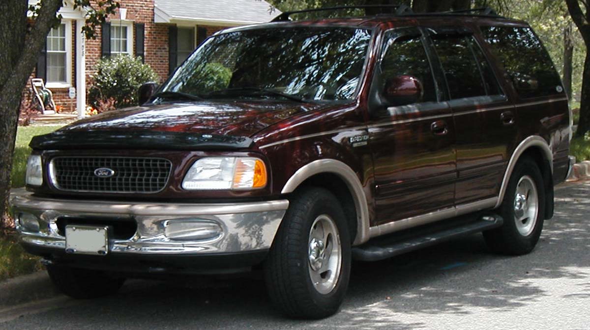
The 1997-2002 Ford Expedition is the first generation of Ford’s full-size SUV. Ford used several under-hood power-distribution layouts during this period, so this guide keeps every source variant separate instead of combining incompatible fuse numbers.
The passenger-compartment fuse panel is located below the dashboard, to the left of the steering wheel near the brake pedal. Later first-generation vehicles, including the 2001 model-year layout represented below, use positions 1-31 plus five relays. The power distribution box is under the hood.
For the second generation, use the Ford Expedition 2003-2006 guide.
Passenger-compartment fuse panel
The table below corresponds to a later first-generation layout, found for example in model year 2001. Earlier vehicles should always be checked against the fuse-box cover or the manual for the exact model year.
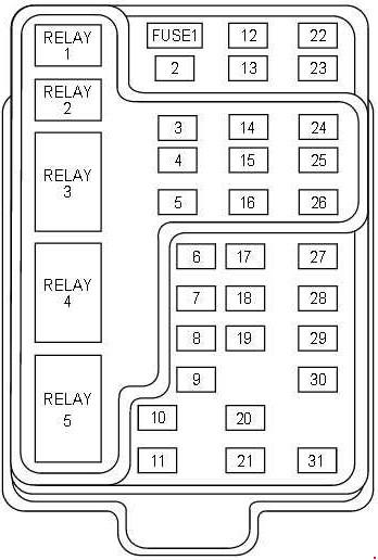
| Position | Rating [A] | Protected component / function |
|---|---|---|
| 1 | 25 | Audio system |
| 2 | 5 | Trip computer, EATC, PCM and instrument cluster |
| 3 | 20 | Cigarette lighter and OBD-II scan-tool connector |
| 4 | 7.5 | Remote-entry module, mirrors and memory functions for seats/pedals |
| 5 | 15 | Speed-control module, reversing lamp, EVO module, climate mode switch/front-blower relay, DRL relay, reverse sensing system, autolock and electrochromic mirror |
| 6 | 5 | Instrument cluster, trip computer, compass, brake-shift interlock solenoid, air-suspension module, GEM, EVO sensor, heated mirror, rear defrost and reverse sensing system |
| 7 | 5 | Auxiliary A/C blower relay – through fuse 22 |
| 8 | 5 | Radio, remote-entry module and GEM |
| 9 | – | Not used |
| 10 | – | Not used |
| 11 | 30 | Front washer-pump relay, wiper run/park relay, wiper high/low relay, windshield-wiper motor and rear washer-pump relay |
| 12 | 15 | Air-suspension switch |
| 13 | 20 | Stop-lamp switch, turn/hazard flasher and speed-control module |
| 14 | 15 | Rear wipers, puddle lamps, battery-saver relay, interior-lamp relay and delayed-accessory relay for power windows/moonroof/flip windows |
| 15 | 5 | Stop-lamp switch inputs for speed control, brake-shift interlock, ABS, PCM, air suspension and autolock; GEM |
| 16 | 20 | Headlamps – high beam; instrument-cluster high-beam indicator |
| 17 | 10 | Heated mirrors and heated-grid switch indicator |
| 18 | 5 | Instrument illumination – dimmer supply |
| 19 | – | Not used |
| 20 | 5 | Audio system, air-suspension module, GEM and memory module |
| 21 | 15 | Starter relay, fuse 20 and transmission range switch |
| 22 | 10 | Airbag module, climate mode switch/blower relay, EATC, EATC blower relay and fuse feed to fuse 7 |
| 23 | 10 | Auxiliary A/C, heated seats, trailer-battery charging, turn/hazard flasher, 4×4 clutch relay, overhead console, electrochromic mirror and 4WABS module |
| 24 | – | Not used |
| 25 | – | Not used |
| 26 | 10 | Right low beam |
| 27 | 5 | Fog-lamp relay and fog-lamp indicator |
| 28 | 10 | Left low beam |
| 29 | 5 | Autolamp module and transmission overdrive-control switch |
| 30 | 30 | Passive Anti-Theft System transceiver, instrument cluster, ignition coils and PCM relay |
| 31 | 10 | Rear integrated audio control panel and CD player |
| Relay 1 | – | Interior-lamp relay |
| Relay 2 | – | Battery-saver relay |
| Relay 3 | – | Rear-window defrost relay |
| Relay 4 | – | One-touch-down window relay |
| Relay 5 | – | Delayed accessory relay |
Engine-compartment power distribution box
Several under-hood layouts were used during the first generation. The physical arrangement and numbering can vary with model year, engine and equipment, so identify the box layout before replacing a fuse.
Under-hood fuse box – variant 1
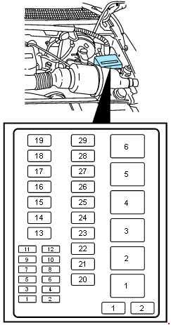
| Position | Rating [A] | Protected component / function |
|---|---|---|
| 1 | 20 | Trailer reversing and tail lamps |
| 2 | 10 | Airbag diagnostic monitor |
| 3 | 30 | Power door locks |
| 4 | 15 | Air suspension |
| 5 | 20 | Horn |
| 6 | 30 | Engine mini fuses 3 and 5 |
| 7 | 15 | Parking and tail lamps |
| 8 | 30 | Headlamps |
| 9 | 15 | Fog lamps and daytime running lamps |
| 10 | 25 | Auxiliary instrument-panel power point |
| 11 | 25 | Auxiliary console power point |
| 12 | 10 | Rear wiper |
| 13 | 30 | Auxiliary blower |
| 14 | 60 | Four-wheel anti-lock brake system (4WABS) |
| 15 | 50 | Air-suspension compressor |
| 16 | 40 | Trailer-battery charging and engine mini fuses 2 and 4 |
| 17 | 30 | 4WD transfer-case motor and clutch |
| 18 | 30 | Driver power seat |
| 19 | 20 | Fuel pump |
| 20 | 50 | Junction-box switched ignition feed |
| 21 | 50 | Junction-box switched ignition feed |
| 22 | 50 | Junction-box battery feed |
| 23 | 40 | Front blower |
| 24 | 30 | Powertrain control module power |
| 25 | 30 C.B. | Power windows |
| 26 | – | Not used |
| 27 | 40 | Heated backlite and mirrors |
| 28 | 30 | Electric trailer brake |
| 29 | 30 | Auxiliary fan, moonroof and flip windows |
| 1 | – | Not used |
| 2 | – | PCM diode |
| 1 | – | Windshield wiper high/low-speed relay |
| 2 | – | Windshield wiper run/park relay |
| 3 | – | Washer-pump relay |
| 4 | – | Fuel-pump relay |
| 5 | – | Horn relay |
| 6 | – | PCM power relay |
Under-hood fuse box – variant 2
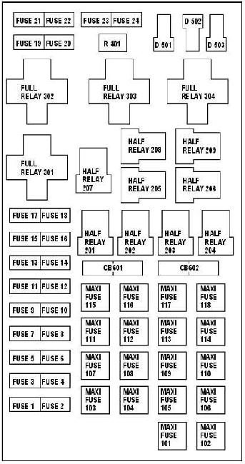
| Position | Rating [A] | Protected component / function |
|---|---|---|
| 1 | 20 | Power point |
| 2 | 30 | Powertrain control module |
| 3 | 30 | Headlamps / autolamps |
| 4 | 20 | Console power point |
| 5 | 20 | Trailer reversing / parking lamps |
| 6 | 15 | Parking lamps / autolamps; passenger-compartment fuse-panel feed |
| 7 | 20 | Horn |
| 8 | 30 | Power door locks |
| 9 | 15 | Daytime running lamps and fog lamps |
| 10 | 20 | Fuel pump |
| 11 | 20 | Alternator field |
| 12 | 10 | Rear wiper |
| 13 | 15 | A/C clutch |
| 14 | – | Not used |
| 15 | 10 | Puddle lamps |
| 16 | – | Not used |
| 17 | 10 | Flip windows |
| 18 | 15 | PCM, fuel injectors, fuel pump and mass-air-flow sensor |
| 19 | 10 | Right trailer stop/turn lamp |
| 20 | 10 | Left trailer stop/turn lamp |
| 21 | – | Not used |
| 22 | – | Not used |
| 23 | 15 | HEGO sensors, canister vent, automatic transmission and CMS sensor |
| 24 | – | Not used |
| 101 | 30 | Trailer-battery charging |
| 102 | 50 | Four-wheel anti-lock brake module |
| 103 | 50 | Junction-box battery feed |
| 104 | 30 | 4×4 shift motor and clutch |
| 105 | 40 | Front A/C blower |
| 106 | – | Not used |
| 107 | – | Not used |
| 108 | 30 | Electric trailer brake |
| 109 | 50 | Air-suspension compressor |
| 110 | 30 | Heated seats |
| 111 | 40 | Ignition-switch battery feed – start circuit |
| 112 | 30 | Driver power seat, adjustable pedals and memory module |
| 113 | 40 | Ignition-switch battery feed – run/accessory circuits |
| 114 | 30 | Auxiliary A/C blower |
| 115 | – | Not used |
| 116 | 40 | Rear-window defroster and heated mirrors |
| 117 | – | Not used |
| 118 | – | Not used |
| 201 | – | Trailer parking-lamp relay |
| 202 | – | Front wiper run/park relay |
| 203 | – | Trailer reversing-lamp relay |
| 204 | – | A/C clutch relay |
| 205 | – | Rear wiper down relay |
| 206 | – | Fog-lamp relay |
| 207 | – | Front washer-pump relay |
| 208 | – | Rear washer-pump relay |
| 209 | – | Rear wiper up relay |
| 301 | – | Fuel-pump relay |
| 302 | – | Trailer-battery-charge relay |
| 303 | – | Wiper high/low relay |
| 304 | – | Powertrain control module relay |
| 401 | – | Not used |
| 501 | – | Powertrain control module diode |
| 502 | – | A/C clutch diode |
| 503 | – | Not used |
| 601 | 30 | Delayed accessories – power windows, flip windows and moonroof |
| 602 | – | Not used |
Engine mini-fuse box
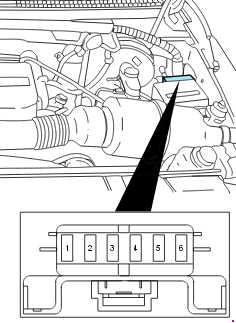
| Position | Rating [A] | Protected component / function |
|---|---|---|
| 1 | 5 | Powertrain control module (PCM) |
| 2 | 20 | Trailer stop/turn lamps |
| 3 | 10 | Rear integrated audio control panel, CD changer and radio |
| 4 | 10 | Puddle lamps |
| 5 | 20 | Amplifier and subwoofer amplifier |
| 6 | – | Not used |
Primary battery fuses
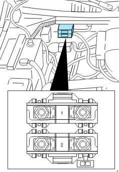
| Position | Rating [A] | Protected component / function |
|---|---|---|
| 1 | 175 | Power distribution box megafuse |
| 2 | 175 | Alternator megafuse |
| 3 | 20 | Alternator-field minifuse |
Commonly checked fuses
For the later first-generation cabin-panel layout, including the MY2001-style arrangement:
- Cigarette lighter / OBD-II connector: cabin fuse 3 – 20 A.
- Radio / audio: cabin fuse 1 – 25 A.
- Front wipers: cabin fuse 11 – 30 A.
- Stop lamps / turn signals: cabin fuse 13 – 20 A.
- Low beams: cabin positions 26 and 28 – 10 A each.
FAQ – Ford Expedition 1997-2002 fuses
Why are there several under-hood fuse-box tables?
The first-generation Expedition used more than one power-distribution layout. The numbering is not interchangeable, so the correct physical layout must be identified first.
Where is the cigarette-lighter fuse in the later cabin-panel layout?
Fuse 3 – 20 A. The same fuse also supplies the OBD-II diagnostic connector.
Where is the fuel-pump fuse?
It depends on the under-hood box variant. Variant 1 uses position 19 – 20 A, while variant 2 uses position 10 – 20 A. The corresponding fuel-pump relays are also retained in the tables.
Can I use the 2003-2006 fuse table for a 2002 Expedition?
No. The second generation uses a different electrical layout.