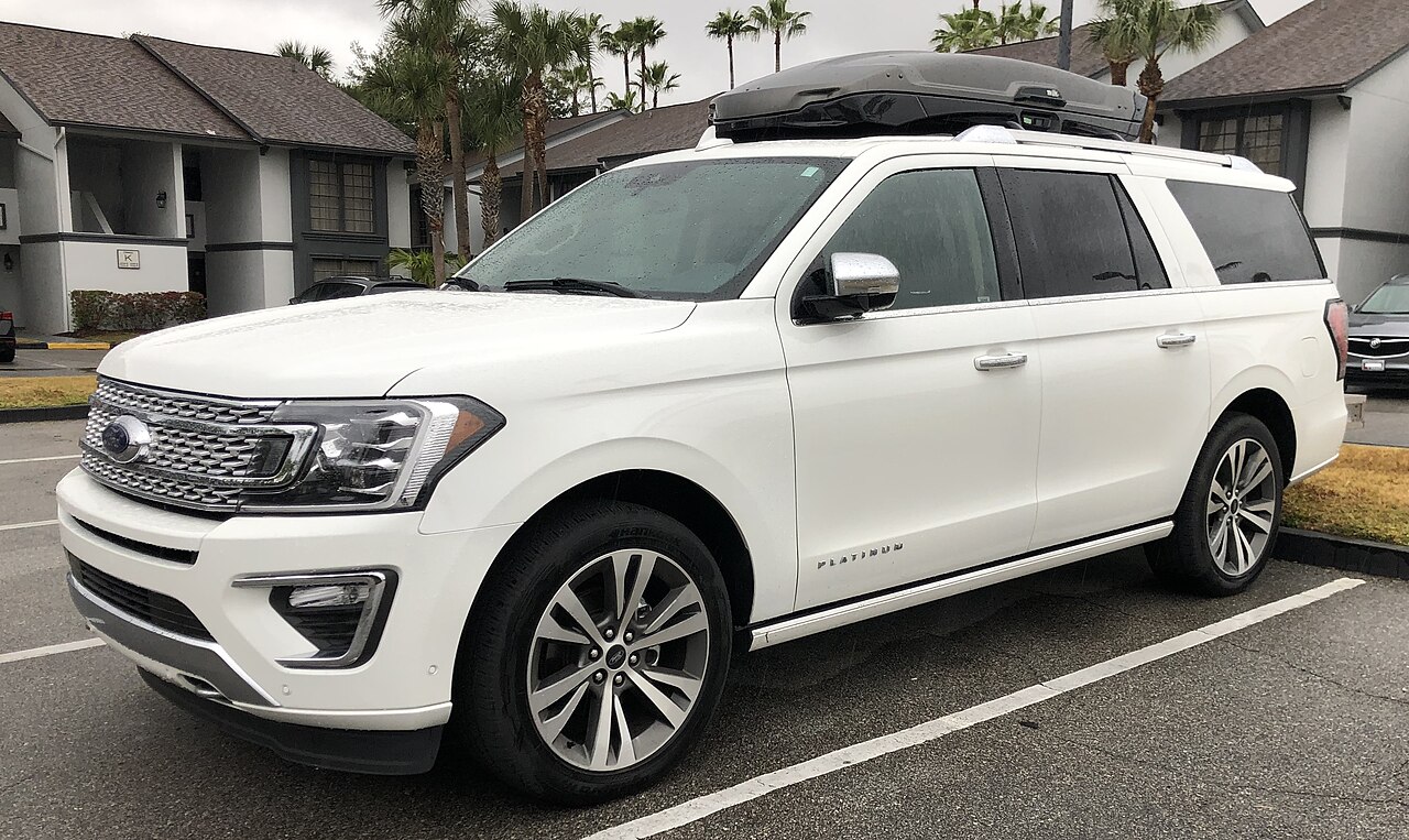
The 2022 Ford Expedition IV, after the fourth-generation facelift, uses two main 12-volt fuse panels: the under-hood power distribution box and the Body Control Module fuse box in the passenger compartment. The 2022 electrical layout differs in several areas from the earlier 2018 Ford Expedition, so fuse numbers should not be carried over between model years without checking the correct table.
The tables below cover the circuits most owners look for first, including the five power points, USB chargers, 4×4 system, electronic limited-slip differential, power running boards, driver-assistance systems, trailer circuits and multi-contour seats. The assignments follow the 2022 Expedition owner information for the North American model; equipment can vary by vehicle and market.
Where are the fuse boxes in a 2022 Ford Expedition?
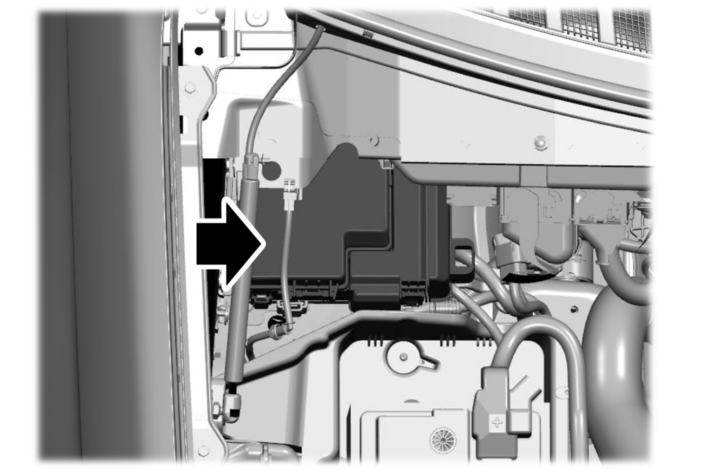
Under-hood fuse box: the power distribution box is located high in the rear area of the engine compartment, close to the cowl, under a large black cover. Release the cover latch to access the fuses. Ford warns that the 12 V battery should be disconnected before servicing high-current fuses.
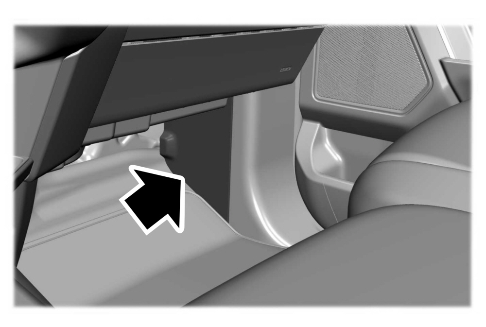
Body Control Module fuse box: this panel is in the front passenger footwell, low under the glove box and behind the side trim panel by the door. This panel protects, among other systems, SYNC, the audio system, wireless charging, drive-mode controls, 4×4 controls and the heated steering wheel.
Under-hood fuse box
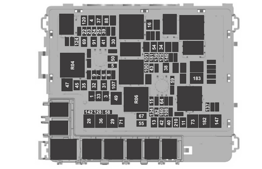
| Fuse / relay | Rating [A] | Protected component / function |
|---|---|---|
| 1 | 30 | Body control module 1 |
| 3 | 30 | Body control module 2 |
| 4 | 30 | Fuel pump |
| 5 | 5 | Powertrain control module relay |
| 6 | 20 | Vehicle power 1 |
| 7 | 25 | Vehicle power 2 |
| 8 | 20 | Vehicle power 3 |
| 9 | 20 | Vehicle power 4 |
| 11 | 30 | Starter relay |
| 13 | 40 | Front blower motor |
| 15 | 20 | Horn |
| 16 | 20 | Windshield washer pump |
| 22 | 10 | Electronic power-assist steering run/start feed |
| 23 | 10 | Anti-lock brake system run/start feed |
| 24 | 10 | Powertrain control module; transmission control module |
| 25 | 10 | Rear-view camera; air-quality sensor run/start feed |
| 28 | 50 | Anti-lock brake system pump |
| 29 | 50 | Anti-lock brake system valves |
| 30 | 30 | Driver seat motors |
| 31 | 30 | Passenger seat motors |
| 32 | 20 | Power point 1 |
| 33 | 20 | Power point 2 |
| 34 | 20 | Power point 3 |
| 35 | 20 | Power point 4 |
| 36 | 40 | Inverter |
| 37 | 30 | Climate-controlled seat – passenger side |
| 38 | 30 | Climate-controlled seat – driver side |
| 39 | 20 | Second-row seat module |
| 40 | 40 | Power running boards |
| 41 | 30 | Power liftgate module |
| 42 | 30 | Trailer brake control module |
| 43 | 5 | Not used (spare) |
| 45 | 20 | Power point 5 |
| 47 | 50 | Electric fan 1 |
| 49 | 50 | Electric fan 2 |
| 50 | 40 | Heated rear window |
| 54 | 40 | Electronic limited-slip differential (eLSD) |
| 55 | 30 | Trailer tow parking lamps relay |
| 58 | 10 | Trailer tow backup lamps |
| 59 | 20 | Not used (spare) |
| 64 | 25 | Four-wheel-drive module 1 |
| 67 | 15 | Transmission run/start |
| 69 | 30 | Left-hand wiper motor |
| 71 | 20 | Rear-window wiper relay |
| 73 | 50 | Power-folding third-row seat module |
| 82 | 25 | Four-wheel-drive module 2 |
| 88 | 40 | Auxiliary blower |
| 91 | 20 | Trailer tow lighting module power |
| 100 | 25 | Left-hand headlamp |
| 101 | 25 | Right-hand headlamp |
| 107 | 30 | Trailer battery charge |
| 108 | 20 | Spot lamps – police vehicles |
| 120 | 15 | Fuel injectors |
| 124 | 5 | Rain sensor module |
| 125 | 5 | USB smart charger 1 |
| 128 | 7.5 | Family entertainment system |
| 134 | 20 | Multi-contour seats relay |
| 137 | 20 | Advanced driver-assistance systems module; connected camera |
| 139 | 5 | USB smart charger 2 |
| 140 | 5 | USB smart charger 3 |
| 142 | 5 | USB smart charger 5 |
| 147 | 40 | Intercooler puller fan relay |
| 160 | 10 | Smart Data Link Connector |
| 181 | 5 | Not used (spare) |
| 182 | 60 | Driver door control module |
| 183 | 60 | Passenger door control module |
| 210 | 30 | Body control module start/stop |
| R04 | relay | Electric fan 1 relay |
| R06 | relay | Electric fan 3 relay |
The 2022 model belongs to the same fourth-generation Expedition family as the 2018 version, but the fuse assignments are not interchangeable. Use the year-specific table when diagnosing a circuit rather than relying on the layout from another model year.
Body Control Module fuse box
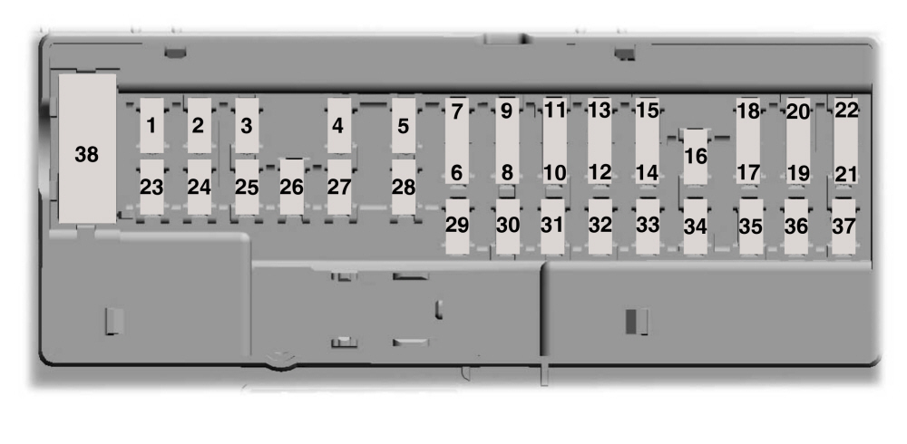
| Fuse | Rating [A] | Protected component / function |
|---|---|---|
| 1 | – | Not used |
| 2 | 10 | Driver seat switch |
| 3 | 7.5 | Driver door unlock |
| 4 | 20 | Speaker amplifier |
| 5 | – | Not used |
| 6 | 10 | Smart Data Link Connector logic |
| 7 | 10 | Rear audio control module |
| 8 | 5 | Wireless accessory charger |
| 9 | 5 | Hands-free liftgate module; keypad; combined sensor module |
| 10 | – | Not used |
| 11 | – | Not used |
| 12 | 7.5 | Instrument cluster |
| 13 | 7.5 | Steering column control module; Smart Data Link Connector logic; climate control module; gear shift module |
| 14 | 15 | Brake switch |
| 15 | 15 | SYNC |
| 16 | – | Not used |
| 17 | – | Not used |
| 18 | 7.5 | Gear shift module; column shifter |
| 19 | 5 | Telematics control unit module |
| 20 | 5 | Ignition switch |
| 21 | 5 | In-vehicle temperature and humidity sensor |
| 22 | 5 | Electrochromic mirror; second-row heated seat module |
| 23 | 30 | Power-window switch; power-mirror switch; left-hand front door zone module |
| 24 | 30 | Moonroof logic |
| 25 | 20 | Speaker amplifier 2 |
| 26 | 30 | Right-hand front door zone module |
| 27 | 30 | Left-hand rear door zone module |
| 28 | 30 | Right-hand rear door zone module |
| 29 | 15 | Adjustable pedals |
| 30 | 5 | Trailer tow control module |
| 31 | 10 | Rear climate control module; drive-mode switch module; Terrain Management switch; radio-frequency transceiver module; 4×4 switch |
| 32 | 20 | Audio control module |
| 33 | – | Not used |
| 34 | 30 | Run/start relay |
| 35 | 5 | Not used (spare) |
| 36 | 15 | Image processing module A; automated park assist module; continuous control damping module |
| 37 | 20 | Heated steering wheel |
| 38 | 30 | Rear power windows – circuit breaker |
Useful circuit references for the 2022 Expedition
- eLSD: fuse 54 – 40 A.
- 4×4: fuses 64 and 82 – 25 A each, plus the 4×4 switch circuit on BCM fuse 31.
- Power running boards: fuse 40 – 40 A.
- Power liftgate: fuse 41 – 30 A; the hands-free liftgate module is also protected by BCM fuse 9.
- USB charging: fuses 125, 139, 140 and 142.
- Trailer circuits: fuses 42, 55, 58, 91 and 107, plus BCM fuse 30.
- Connected camera / ADAS: fuse 137 – 20 A.
FAQ – 2022 Ford Expedition fuses
What should I check if the power running boards do not deploy?
The main fuse for the power running boards is fuse 40 – 40 A in the under-hood box. If it is intact, check the running-board module, door-status inputs and the mechanical drive.
Why can one 12 V power point fail while the others still work?
The Expedition uses separate protection for its power points. Fuses 32, 33, 34, 35 and 45 protect different outlets, so a fault in one circuit does not necessarily affect the others.
What should I check if the connected camera and some driver-assistance functions stop working?
Fuse 137 – 20 A in the under-hood box is one of the first circuits to inspect. It supplies the advanced driver-assistance systems module and the connected camera.
Why can drive-mode and 4×4 problems appear at the same time?
BCM fuse 31 – 10 A supplies the rear climate control module, drive-mode switch module, Terrain Management switch, radio-frequency transceiver and 4×4 switch. If several of these functions fail together, this circuit is a useful starting point.
Can I use the 2018 Expedition fuse chart for a 2022 model?
No. Both vehicles belong to the same generation, but the 2022 facelift brought equipment and electrical-assignment changes. Use the fuse chart for the correct model year.