
The sixth-generation Ford Taurus (2009-2017) uses two main fuse boxes, but their numbering and several assignments changed after the facelift. For that reason the complete tables are separated into the 2009-2012 and 2013-2017 electrical layouts.
SHO models with the 3.5 EcoBoost use some different high-current circuits from naturally aspirated 3.5 V6 versions, particularly for cooling fans, engine management and turbo-related equipment. Always match the fuse to the model year and engine.
For the preceding model, see the Ford Taurus 2008-2009 fuse guide.
Where are the fuse boxes?
Passenger compartment: below the dashboard to the left of the steering wheel. On later model years, access may require removing the lower trim panel.
Engine compartment: under the black cover in the power distribution box. It contains the high-current fuses and relays for ABS, starter, fuel pump, cooling fans, seats and PCM circuits.
Passenger-compartment fuse panel – 2009-2012
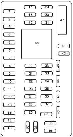
| Position | Rating [A] | Protected component / function |
|---|---|---|
| 1 | 30 | Left front Smart Window motor |
| 2 | 15 | Stop-lamp switch |
| 3 | 15 | Driver power seat |
| 4 | 30 | Right front Smart Window motor |
| 5 | 10 | Transmission selector solenoid, keypad |
| 6 | 20 | Turn signals and hazard lamps |
| 7 | 10 | Left low beam |
| 8 | 10 | Right low beam |
| 9 | 15 | Interior and luggage-compartment lighting |
| 10 | 15 | Switch illumination, puddle lamps |
| 11 | 10 | AWD module |
| 12 | 7.5 | Intelligent Access module |
| 13 | 5 | Memory seats, mirrors, keypad, IA receiver, driver-door module |
| 14 | 10 | Navigation, memory seat, SYNC, center display, GPS |
| 15 | 10 | Climate control |
| 16 | 15 | Electronic finish panel, ambient lighting |
| 17 | 20 | Luggage-compartment release, moonroof, Smart Windows, central locking |
| 18 | 20 | Rear heated seats |
| 19 | 25 | Audio amplifier |
| 20 | 15 | OBD-II diagnostic connector, adjustable pedals |
| 21 | 15 | Daytime running-lamp control |
| 22 | 15 | Parking, license-plate and auxiliary lamps |
| 23 | 15 | High beams |
| 24 | 20 | Horn |
| 25 | 10 | Demand lighting / battery saver |
| 26 | 10 | Instrument cluster, head-up display |
| 27 | 20 | Ignition switch, Intelligent Access, front wipers, OTIS |
| 28 | 5 | Start relay / audio mute |
| 29 | 5 | Instrument cluster, head-up display |
| 30 | 5 | Spare |
| 31 | 10 | Spare |
| 32 | 10 | Airbag module |
| 33 | 10 | Spare |
| 34 | 5 | ABS, electric power steering |
| 35 | 10 | Rear heated seats, AWD, park assist, steering-angle sensor, BLIS, multi-contour seats |
| 36 | 5 | PATS |
| 37 | 10 | Spare |
| 38 | 20 | Subwoofer, speaker amplifier |
| 39 | 20 | Radio / navigation |
| 40 | 20 | Spare |
| 41 | 15 | Delayed accessory power |
| 42 | 10 | Spare |
| 43 | 10 | Heated rear window, wipers, automatic high beams, rain sensor |
| 44 | 10 | Spare |
| 45 | 5 | Front-wiper relay, blower relay |
| 46 | 7.5 | Occupant Classification System, passenger-airbag deactivation indicator |
| 47 | 30 | Circuit breaker – passenger front window and rear windows |
| 48 | Relay | Delayed accessory power |
Engine-compartment power distribution box – 2009-2012
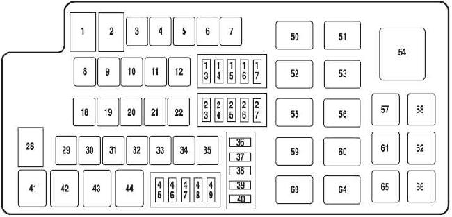
| Position | Rating [A] | Protected component / function |
|---|---|---|
| 1 | 80 | Passenger fuse-panel supply |
| 2 | 80 | Passenger fuse-panel supply |
| 3 | – | Not used |
| 4 | 30 | Front wipers |
| 5 | 30 | Passenger seat |
| 6 | 20 | Cigarette lighter |
| 7 | 60 | Cooling fan – non-SHO engine |
| 8 | 30 | Moonroof |
| 9 | 40 | ABS pump |
| 10 | 30 | Starter relay |
| 11 | 30 | PCM relay |
| 12 | 20 | ABS valves |
| 13 | 15 | Adaptive cruise control |
| 14 | – | Not used |
| 15 | – | Not used |
| 16 | 20 | Left headlamp |
| 17 | 10 | Alternator |
| 18 | – | Not used |
| 19 | 20 | Dashboard power outlet |
| 20 | 40 | Heated rear window |
| 21 | 20 | Console power outlet |
| 22 | 30 | Heated / climate-controlled front seats |
| 23 | 7.5 | PCM keep-alive memory, EVAP valve |
| 24 | 10 | A/C clutch |
| 25 | 20 | Right headlamp |
| 26 | 10 | Reversing-lamp relay |
| 27 | 25 | Fuel pump |
| 28 | 80 | Cooling fan – SHO |
| 29 | – | Not used |
| 30 | – | Not used |
| 31 | – | Not used |
| 32 | 30 | Driver seat |
| 33 | 30 | Intelligent Access |
| 34 | – | Not used |
| 35 | 40 | Front blower |
| 36 | 20 | Passenger fuse panel – RUN/START |
| 37 | 10 | PCM relay |
| 38 | 5 | Delayed accessory power |
| 39 | Diode | Fuel-pump diode – iVCT |
| 40 | Diode | OTIS diode |
| 41 | Relay | A/C clutch |
| 42 | Relay | Fuel pump |
| 43 | Relay | Reversing lamps |
| 44 | – | Not used |
| 45 | – | Not used |
| 46 | 15 | Vehicle Power 2 and 3 – PCM |
| 47 | 20 | Vehicle Power 1 – PCM |
| 48 | 20 | Vehicle Power 4 – ignition coils |
| 49 | 15 | Heated mirrors |
| 50 | Relay | Blower |
| 51 | Relay | Center high-mounted stop lamp with ACCM |
| 52 | Relay | Starter |
| 53 | Relay | PCM power |
| 54 | – | Not used |
| 55 | Relay | Front wipers |
| 56 | Relay | Heated rear window |
| 57 | – | Not used |
| 58 | – | Not used |
| 59 | Relay | Left halogen headlamp |
| 60 | Relay | Right halogen headlamp |
| 61 | – | Not used |
| 62 | – | Not used |
| 63 | Relay | DRL 1 |
| 64 | Relay | DRL 2 / high-beam control |
| 65 | Relay | RUN/START – Intelligent Access |
| 66 | – | Not used |
Passenger-compartment fuse panel – 2013-2017
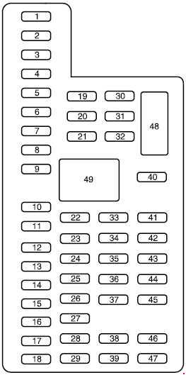
| Position | Rating [A] | Protected component / function |
|---|---|---|
| 1 | 30 | Left front and right rear Smart Window motors |
| 2 | 15 | Driver-seat switch |
| 3 | 30 | Right front Smart Window |
| 4 | 10 | Demand lighting / battery saver |
| 5 | 20 | Audio amplifier |
| 6 | 5 | Spare |
| 7 | 7.5 | Driver-seat logic, left front door module, keypad |
| 8 | 10 | Spare |
| 9 | 10 | SYNC, displays, electronic finish panel, RF module |
| 10 | 10 | Accessory relay |
| 11 | 10 | Intelligent Access logic, head-up display |
| 12 | 15 | Puddle lamps, LED and interior lighting |
| 13 | 15 | Right turn signals |
| 14 | 15 | Left turn signals |
| 15 | 15 | Stop and reversing lamps |
| 16 | 10 | Right low beam |
| 17 | 10 | Left low beam |
| 18 | 10 | START button, keypad illumination, shift interlock, PCM wake-up, immobilizer |
| 19 | 20 | Audio amplifiers |
| 20 | 20 | Central-lock motor relays |
| 21 | 10 | Extended power module |
| 22 | 20 | Horn relay |
| 23 | 15 | Steering-column module logic, instrument cluster |
| 24 | 15 | Steering-column module, data link |
| 25 | 15 | Luggage-compartment lid release |
| 26 | 5 | Ignition switch / START button |
| 27 | 20 | Intelligent Access supply |
| 28 | 15 | Spare |
| 29 | 20 | Radio, GPS |
| 30 | 15 | Front parking lamps |
| 31 | 5 | Spare |
| 32 | 15 | Smart Windows, master window/mirror switch, rear-window sunshade |
| 33 | 10 | Spare |
| 34 | 10 | Park assist, automatic high beams / Lane Departure, rear heated seats, BLIS, rear-view camera |
| 35 | 5 | Humidity sensor, head-up display, traction-control switch |
| 36 | 10 | Heated steering wheel |
| 37 | 10 | Spare |
| 38 | 10 | Electrochromic mirror, moonroof module |
| 39 | 15 | High beams |
| 40 | 10 | Rear parking lamps |
| 41 | 7.5 | Extended power module |
| 42 | 5 | Spare |
| 43 | 10 | Spare |
| 44 | 10 | Spare |
| 45 | 5 | Spare |
| 46 | 10 | Climate-control module |
| 47 | 15 | Spare |
| 48 | 30 | Circuit breaker – passenger front window and rear windows |
| 49 | Relay | Delayed accessory power |
Engine-compartment power distribution box – 2013-2017
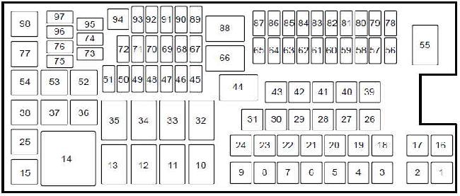
| Position | Rating [A] | Protected component / function |
|---|---|---|
| 1 | – | Not used |
| 2 | – | Not used |
| 3 | – | Not used |
| 4 | 30 | Wiper-motor relay |
| 5 | 50 | ABS pump |
| 6 | – | Not used |
| 7 | – | Not used |
| 8 | 20 | Moonroof, power sunshade |
| 9 | 20 | Second-row power outlet |
| 10 | – | Not used |
| 11 | Relay | Heated rear window |
| 12 | – | Not used |
| 13 | Relay | Starter |
| 14 | Relay | Left cooling fan 2 |
| 15 | Relay | Fuel pump |
| 16 | – | Not used |
| 17 | – | Not used |
| 18 | 40 | Front blower motor |
| 19 | 30 | Starter relay |
| 20 | 20 | Glove-box power outlet |
| 21 | 20 | Rear heated seats |
| 22 | – | Not used |
| 23 | 30 | Driver seat, memory module |
| 24 | – | Not used |
| 25 | – | Not used |
| 26 | 40 | Heated rear window |
| 27 | 20 | Cigarette lighter |
| 28 | 30 | Climate-controlled seats |
| 29 | 40 | Electric fan 1 |
| 30 | 40 | Electric fan 2 |
| 31 | 25 | Electric fan 3 |
| 32 | Relay | Multi-contour / massage seats |
| 33 | Relay | Right cooling fan |
| 34 | Relay | Blower |
| 35 | Relay | Left cooling fan 1 |
| 36 | – | Not used |
| 37 | – | Not used |
| 38 | – | Not used |
| 39 | – | Not used |
| 40 | – | Not used |
| 41 | – | Not used |
| 42 | 30 | Passenger seat |
| 43 | 20 | ABS valves |
| 44 | – | Not used |
| 45 | 5 | Rain sensor |
| 46 | – | Not used |
| 47 | – | Not used |
| 48 | – | Not used |
| 49 | – | Not used |
| 50 | 15 | Heated mirrors |
| 51 | – | Not used |
| 52 | – | Not used |
| 53 | – | Not used |
| 54 | – | Not used |
| 55 | Relay | Wipers |
| 56 | – | Not used |
| 57 | 20 | Left HID headlamp |
| 58 | 10 | Alternator A-line |
| 59 | 10 | Stop-lamp switch |
| 60 | – | Not used |
| 61 | – | Not used |
| 62 | 10 | A/C clutch relay |
| 63 | – | Not used |
| 64 | 15 | Multi-contour / massage seats |
| 65 | 30 | Fuel-pump relay, fuel injectors |
| 66 | Relay | PCM |
| 67 | 20 | Oxygen-sensor heaters, MAF, VCT, EVAP |
| 68 | 20 | Ignition coils |
| 69 | 20 | Vehicle Power 1 – PCM |
| 70 | 15 | A/C clutch, fan coils, compressor, AWD and EcoBoost controls |
| 71 | – | Not used |
| 72 | – | Not used |
| 73 | – | Not used |
| 74 | – | Not used |
| 75 | – | Not used |
| 76 | – | Not used |
| 77 | – | Not used |
| 78 | 20 | Right HID headlamp |
| 79 | – | Not used |
| 80 | – | Not used |
| 81 | – | Not used |
| 82 | – | Not used |
| 83 | – | Not used |
| 84 | – | Not used |
| 85 | – | Not used |
| 86 | 7.5 | PCM keep-alive memory and relay, EVAP valve |
| 87 | 5 | RUN/START relay |
| 88 | Relay | RUN/START |
| 89 | 5 | Blower-relay coil, electric power steering |
| 90 | 10 | PCM – RUN/START |
| 91 | 10 | Adaptive cruise control |
| 92 | 10 | ABS module |
| 93 | 5 | Heated rear-window relay |
| 94 | 30 | Passenger fuse panel – RUN/START |
| 95 | – | Not used |
| 96 | – | Not used |
| 97 | – | Not used |
| 98 | Relay | A/C clutch |
FAQ – Ford Taurus 2009-2017 fuses
Why is the fuel-pump fuse different between 2012 and 2017?
Ford redesigned the power distribution box after the facelift. In the 2009-2012 layout the fuel pump uses position 27 – 25 A. In the 2013-2017 layout the fuel-pump relay and injectors use position 65 – 30 A, together with a separate relay.
Does the SHO use the same cooling-fan fuse as the standard 3.5 V6?
Not in the earlier layout. Position 7 – 60 A is used for the non-SHO cooling fan, while position 28 – 80 A is associated with the SHO cooling fan. The 2013-2017 box splits fan circuits across positions 29, 30 and 31.
Where is the OBD-II fuse on 2009-2012 cars?
Cabin position 20 – 15 A supplies the diagnostic connector and adjustable pedals.
BLIS, rear camera and park assist stopped working together – which fuse should I check?
On 2013-2017 cars, cabin position 34 – 10 A supplies BLIS, the rear-view camera, park assist and related driver-assistance functions.
Can I use the 2017 diagram for a 2010 Taurus?
No. The facelift changed both numbering and circuit assignments, which is why both complete layouts are retained separately.