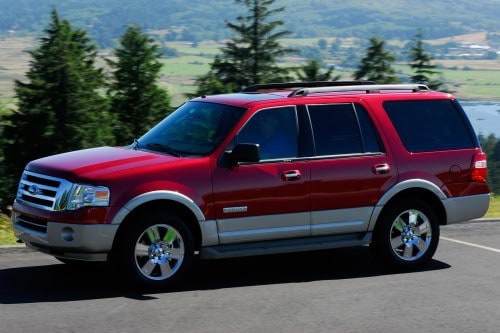
The 2009-2014 Ford Expedition uses two main fuse locations: the passenger-compartment fuse panel under the right-hand side of the dashboard and the engine-compartment power distribution box. The numbering remains broadly similar throughout this period, but Ford changed several assignments as equipment and model years evolved.
If you have an earlier third-generation vehicle, use the separate Ford Expedition 2007-2008 guide. For facelifted 2015-2017 vehicles, use the Ford Expedition 2015-2017 tables instead.
Important: the tables are based primarily on Ford’s 2014 factory documentation. Where 2009 or 2011 manuals show a different assignment, the model-year difference is retained explicitly rather than merged away.
Passenger-compartment fuse panel
The panel is located below the right-hand side of the dashboard behind the passenger-side trim panel.
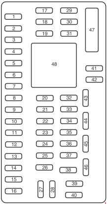
| Position | Rating [A] | Protected component / function |
|---|---|---|
| 1 | 30 | Driver power window |
| 2 | 15 | Driver-seat memory module |
| 3 | 15 | Rear-seat audio controls, satellite radio, SYNC |
| 4 | 30 | 2009: second one-touch window. 2011-2014: spare / not used |
| 5 | 10 | Keypad illumination, third-row seat enable, brake-shift interlock, smart junction-box logic |
| 6 | 20 | Turn signals |
| 7 | 10 | Left low beam |
| 8 | 10 | Right low beam |
| 9 | 15 | Interior lighting |
| 10 | 15 | Switch illumination and puddle lamps |
| 11 | 10 | Spare |
| 12 | 7.5 | Power mirrors, driver-seat memory switch |
| 13 | 5 | Spare |
| 14 | 10 | Power liftgate module – keep-alive power |
| 15 | 10 | Climate control; later model years also GPS module |
| 16 | 15 | Spare |
| 17 | 20 | Door locks, liftgate release and liftgate-glass release |
| 18 | 20 | Second-row heated seats |
| 19 | 25 | Rear wiper |
| 20 | 15 | Adjustable pedals, diagnostic connector |
| 21 | 15 | Front fog lamps; 2009 also cornering lamps |
| 22 | 15 | Parking lamps |
| 23 | 15 | High beams |
| 24 | 20 | Horn |
| 25 | 10 | Demand lamps, glove box, vanity mirrors |
| 26 | 10 | Instrument cluster |
| 27 | 20 | Ignition switch |
| 28 | 5 | Radio |
| 29 | 5 | Instrument cluster |
| 30 | 5 | Spare |
| 31 | 10 | Spare |
| 32 | 10 | Airbag module |
| 33 | 10 | 2009-2011: spare. 2013-2014: trailer-brake controller logic |
| 34 | 5 | Spare |
| 35 | 10 | Rear parking aid, 4×4 module, rear-view camera; later model years also second-row heated seats |
| 36 | 5 | Immobilizer / Passive Anti-Theft System |
| 37 | 10 | Climate control |
| 38 | 20 | Subwoofer |
| 39 | 20 | Radio |
| 40 | 20 | Navigation amplifier |
| 41 | 15 | Power windows, rear vent windows, moonroof, electrochromic mirror; later model years also 110 V outlet |
| 42 | 10 | Spare |
| 43 | 10 | Rear-wiper control, rain sensor |
| 44 | 10 | Trailer-battery-charge relay coil |
| 45 | 5 | Front-wiper control |
| 46 | 7.5 | Climate control, auxiliary-relay control |
| 47 | 30 | Power-window and moonroof circuit breaker |
| 48 | Relay | Delayed accessory power |
Engine-compartment power distribution box
The under-hood power distribution box contains high-current fuses and relays for the starter, fuel pump, ABS, wipers, cooling fans, seats and trailer equipment.
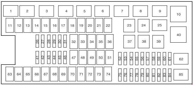
| Position | Rating [A] | Protected component / function |
|---|---|---|
| 1 | Relay | Powertrain control module (PCM) |
| 2 | Relay | Starter |
| 3 | Relay | Blower motor |
| 4 | Relay | Trailer battery charging |
| 5 | Relay | Fuel pump |
| 6 | Relay | Cooling fan No. 1 |
| 7 | Relay | Heated rear window and heated mirrors |
| 8 | Relay | Cooling fan No. 3 |
| 9 | Relay | RUN/START |
| 10 | Relay | 2011: rear air suspension. 2014: not used |
| 11 | 40 | Power running boards |
| 12 | 40 | RUN/START relay |
| 13 | 30 | Starter relay |
| 14 | 40 | Cooling fan |
| 15 | – | Not used |
| 16 | 40 | Cooling fan |
| 17 | – | Not used |
| 18 | 30 | Trailer-brake controller |
| 19 | 60 / – | 2011: rear air-suspension supply, 60 A. 2014: not used |
| 20 | 20 | 4×4 module |
| 21 | 30 | Trailer battery charging |
| 22 | 30 | Passenger power seat |
| 23 | Relay | A/C compressor clutch |
| 24 | Relay | Trailer parking lamps |
| 25 | – | Not used |
| 26 | 15 / – | 2011: transmission control module keep-alive memory, 15 A. 2014: not used |
| 27 | 20 | 4×4 system |
| 28 | 25 | Trailer parking lamps |
| 29 | 20 | Reversing lamps, integrated wheel-end solenoid |
| 30 | 10 | A/C compressor clutch |
| 31 | – | Not used |
| 32 | 40 | Blower-motor relay |
| 33 | 40 | 110 V AC power outlet |
| 34 | 30 | Auxiliary blower motor |
| 35 | 30 | PCM relay |
| 36 | 30 | Power liftgate |
| 37 | Relay | Left trailer turn/stop lamp |
| 38 | Relay | Right trailer turn/stop lamp |
| 39 | Relay | Reversing lamps |
| 40 | Relay | Cooling fan No. 2 |
| 41 | 10 | PCM keep-alive memory |
| 42 | – | Not used |
| 43 | 5 | Stop-lamp switch |
| 44 | 20 | Fuel-pump relay |
| 45 | 25 | Trailer stop/turn lamps |
| 46 | – | Not used |
| 47 | – | Not used |
| 48 | 30 / – | 2011: rear air-suspension module, 30 A. 2014: not used |
| 49 | – | Not used |
| 50 | 30 | Front wiper-motor relay |
| 51 | 40 | Heated rear window and heated mirrors |
| 52 | 10 | ABS RUN/START supply |
| 53 | 10 / – | 2011: rear air-suspension module, 10 A. 2014: not used |
| 54 | 5 / – | 2011: transmission controller RUN/START supply, 5 A. 2014: not used |
| 55 | 5 | Fuel-pump relay coil – RUN/START |
| 56 | 30 | Passenger fuse-panel RUN/START supply |
| 57 | 10 | Blower-relay coil |
| 58 | 15 | Trailer reversing lamps |
| 59 | 15 | Heated mirrors |
| 60 | Diode / – | 2011: one-touch-start system diode. 2014: not used |
| 61 | Diode | Fuel pump |
| 62 | – | Not used |
| 63 | 25 | Cooling fan |
| 64 | 30 | Moonroof |
| 65 | 20 | Dashboard auxiliary power outlet |
| 66 | 20 | Rear center-console auxiliary power outlet |
| 67 | 40 | Climate-controlled front seats |
| 68 | 60 | ABS valves |
| 69 | 60 | ABS pump |
| 70 | 40 / 30 | Power-fold third-row seats: 40 A in 2011, 30 A in 2014 |
| 71 | 20 | Auxiliary power outlet / cigarette lighter |
| 72 | 20 | Right rear-quarter auxiliary power outlet |
| 73 | – | Not used |
| 74 | 30 | Driver power seat |
| 75 | 20 | Vehicle power 1 – PCM |
| 76 | 20 | Vehicle power 2 – PCM |
| 77 | 15 | Vehicle power 4 – ignition coils |
| 78 | – | Not used |
| 79 | 20 | Vehicle power 3 – PCM |
| 80 | – | Not used |
| 81 | – | Not used |
| 82 | – | Not used |
| 83 | – | Not used |
| 84 | – | Not used |
| 85 | Relay | Wiper motor |
Important model-year differences
The biggest changes concern optional equipment, rear air suspension and transmission-control circuits. In 2009, cabin fuse 4 supplies the second one-touch window, while later manuals list it as spare. By 2013-2014, cabin fuse 33 is used for trailer-brake controller logic. Under the hood, several 2011 rear-air-suspension positions – 10, 19, 48 and 53 – are listed as unused in the 2014 documentation.
For the older second generation, use the Ford Expedition 2003-2006 guide because its numbering and box layout are substantially different.
Commonly checked fuses
- Cigarette lighter / 12 V outlet: position 71 – 20 A under the hood.
- Dashboard outlet: position 65 – 20 A.
- Rear center-console outlet: position 66 – 20 A.
- Right rear-quarter outlet: position 72 – 20 A.
- Fuel pump: relay 5 and fuse 44 – 20 A.
- Radio: cabin positions 39 – 20 A and 28 – 5 A.
- Horn: cabin position 24 – 20 A.
- Low beams: cabin positions 7 and 8 – 10 A each.
FAQ – Ford Expedition 2009-2014 fuses
Where is the passenger fuse panel?
Below the right-hand side of the dashboard behind the passenger-side trim panel.
Where is the cigarette-lighter fuse?
Under-hood position 71 – 20 A. Other power outlets use positions 65, 66 and 72.
Where is the fuel-pump fuse?
The fuel-pump relay is position 5, with fuse 44 – 20 A supplying the relay circuit.
Which positions changed with rear air suspension?
Several 2011 assignments – notably positions 10, 19, 48 and 53 – are associated with rear air suspension but are unused in the 2014 documentation.
Can I use this table for a 2015 Expedition?
No. The 2015 facelift changed multiple assignments, so use the dedicated 2015-2017 guide.