
The 2015-2017 Ford Expedition has two main fuse locations: a passenger-compartment fuse panel and an engine-compartment power distribution box. The layout below applies to the facelifted third-generation Expedition for model years 2015, 2016 and 2017.
The cabin panel protects systems such as the windows, lighting, radio, SYNC, horn and convenience modules. The under-hood power distribution box carries the high-current circuits for the cooling fans, ABS, fuel pump, wipers, heated glass and trailer equipment.
For the earlier version of this generation, see the Ford Expedition 2009-2014 guide. The later Ford Expedition IV 2018 uses a different electrical architecture.
Passenger-compartment fuse panel
The panel is located on the passenger side below the dashboard. Ford changed several positions between the 2015 model year and 2016-2017, so the year-specific assignments are retained explicitly in the table.
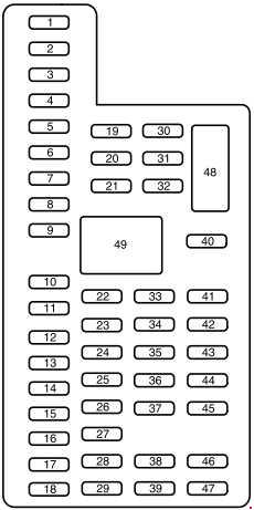
| Position | Rating [A] | Protected component / function |
|---|---|---|
| 1 | 30 | Driver power window |
| 2 | 15 | Rear-seat controls, media gateway module |
| 3 | 30 | Passenger power window |
| 4 | 10 | Demand lamps |
| 5 | 20 | Audio amplifier |
| 6 | 5 | Rear electronic climate control |
| 7 | 7.5 | Power mirrors, driver-seat memory switch |
| 8 | – | Not used |
| 9 | 10 | SYNC, power liftgate, finish panel, display |
| 10 | 10 | Accessory-delay relay |
| 11 | 10 | Passive-entry / passive-start module |
| 12 | 15 | Interior lamps and puddle/scuff lamps |
| 13 | 15 | Right turn signals and right stop/turn lamps |
| 14 | 15 | Left turn signals and left stop/turn lamps |
| 15 | 15 | Reversing lamps, high-mounted stop lamp, electrochromic mirror |
| 16 | 10 | Right front low beam |
| 17 | 10 | Left front low beam |
| 18 | 10 | Brake-shift interlock, START/keypad illumination, power-fold third-row seat, keyless system |
| 19 | – | Not used |
| 20 | 20 | Central-lock relays – lock and unlock |
| 21 | – | Not used |
| 22 | 20 | Horn |
| 23 | 15 | Steering-wheel controls and instrument cluster |
| 24 | 15 | Adjustable pedals / power steering column, diagnostic connector |
| 25 | 15 | Liftgate release and liftgate-glass release motor |
| 26 | 5 | Engine start button |
| 27 | 20 | Passive-entry / passive-start module |
| 28 | 15 | Ignition switch and key interlock |
| 29 | 20 | Radio and GPS |
| 30 | 15 | Front parking lamps |
| 31 | 5 | Trailer-brake controller on/off signal |
| 32 | 15 | 2015: power vent windows, rear windows and power inverter. 2016-2017: power vent windows, driver-window motor and power inverter |
| 33 | 10 | CCD suspension module |
| 34 | 10 | Rear parking sensors, rear-view camera, BLIS, heated-seat system |
| 35 | 5 | Climate-control module and overdrive switch |
| 36 | – | Not used |
| 37 | 10 | 4×4 module |
| 38 | 10 | Electrochromic mirror, moonroof, DVD and AM/FM radio |
| 39 | 15 | Left and right high beams |
| 40 | 10 | Rear parking and marker lamps |
| 41 | 7.5 | Restraints control module |
| 42 | – | Not used |
| 43 | – | Not used |
| 44 | – | Not used |
| 45 | 5 | Spare |
| 46 | 10 | Climate control |
| 47 | 15 | Front fog lamps |
| 48 | – / 30 | 2015: not used. 2016-2017: 30 A circuit breaker for passenger front window and rear windows |
| 49 | – / Relay | 2015: not used. 2016-2017: delayed accessory relay for windows and vent windows |
Engine-compartment power distribution box
This box contains high-current fuses and relays for the vehicle’s major electrical systems. Ford recommends disconnecting the battery before servicing high-current fuses.
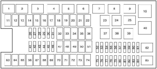
| Position | Rating [A] | Protected component / function |
|---|---|---|
| 1 | Relay | Rear washer pump |
| 2 | Relay | Starter |
| 3 | Relay | Blower motor |
| 4 | Relay | Rear wiper |
| 5 | Relay | Fuel pump |
| 6 | Relay | Electronic cooling fan |
| 7 | Relay | Heated rear window and heated mirrors |
| 8 | Relay | Electronic cooling fan |
| 9 | Relay | RUN/START |
| 10 | Relay | Power distribution box relay |
| 11 | 40 | Power running boards, heated seats |
| 12 | 40 | RUN/START relay |
| 13 | 30 | Starter relay |
| 14 | 50 | Electronic cooling fan |
| 15 | – | Not used |
| 16 | 50 | Electronic cooling fan |
| 17 | – | Not used |
| 18 | 30 | Trailer brake |
| 19 | 20 | Console power point |
| 20 | 20 | 4×4 HAT 2 module |
| 21 | 30 | Trailer-tow module |
| 22 | 30 | Passenger power seat |
| 23 | Relay | A/C compressor clutch |
| 24 | Relay | Trailer parking lamps |
| 25 | – | Not used |
| 26 | 10 | Alternator sensor |
| 27 | 20 | 4×4 HAT 1 module |
| 28 | 25 | Trailer parking-lamp relay |
| 29 | 10 | Integrated wheel-end solenoid |
| 30 | 10 | A/C compressor clutch |
| 31 | 15 | Trailer reversing lamps |
| 32 | 40 | Blower-motor relay |
| 33 | 40 | 110 V AC power point |
| 34 | 30 | Auxiliary blower motor |
| 35 | 50 | PCM relay |
| 36 | 30 | Power liftgate |
| 37 | – | Not used |
| 38 | – | Not used |
| 39 | Relay | Trailer reversing lamps |
| 40 | Relay | Second electronic cooling fan |
| 41 | 10 | PCM keep-alive memory |
| 42 | 5 | RUN/START relay |
| 43 | 10 | Stop-lamp switch |
| 44 | 20 | Fuel-pump relay |
| 45 | 10 | Spare |
| 46 | 15 | Front and rear washer pump |
| 47 | 30 | Rear wiper motor |
| 48 | 40 | Trailer-tow module |
| 49 | – | Not used |
| 50 | 30 | Front wiper-motor relay |
| 51 | 40 | Heated rear window and heated mirrors |
| 52 | 10 | ABS RUN/START feed |
| 53 | 5 | PCM – ISP |
| 54 | 5 | Electric power steering |
| 55 | – | Not used |
| 56 | 30 | Passenger fuse-panel RUN/START feed |
| 57 | 5 | Blower-motor RUN/START feed |
| 58 | – | Not used |
| 59 | 15 | Heated mirrors |
| 60 | – | Not used |
| 61 | – | Not used |
| 62 | – | Not used |
| 63 | 25 | Electronic cooling fan |
| 64 | 30 | Moonroof |
| 65 | 20 | Spare |
| 66 | 20 | Auxiliary power point at rear of center console |
| 67 | 40 | Climate-controlled/heated front seats |
| 68 | 30 | ABS valves |
| 69 | 60 | ABS pump |
| 70 | 30 | Power-fold third-row seats |
| 71 | 20 | Auxiliary power point / cigarette lighter |
| 72 | 20 | Auxiliary power point in right rear quarter panel |
| 73 | 30 / 20 | Rear climate-control module: 30 A in 2015; 20 A in 2016-2017 |
| 74 | 30 | Driver power seat |
| 75 | 25 | Vehicle power 1 – PCM |
| 76 | 20 | Vehicle power 2 – PCM |
| 77 | 20 | Vehicle power 4 – ignition coils |
| 78 | – | Not used |
| 79 | 15 | Vehicle power 3 – PCM |
| 80 | 5 / – | 2015: rain sensor, 5 A. 2016-2017: not used |
| 81 | – | Not used |
| 82 | – / 5 | 2015: not used. 2016-2017: rain sensor, 5 A |
| 83 | – | Not used |
| 84 | – | Not used |
| 85 | – / Relay | 2015: not used. 2016-2017: wiper-motor relay |
Commonly checked fuses
- Cigarette lighter / 12 V outlet: under-hood position 71 – 20 A.
- Console power point: position 19 – 20 A.
- Rear center-console power point: position 66 – 20 A.
- Right rear-quarter power point: position 72 – 20 A.
- Fuel pump: relay position 5 and fuse 44 – 20 A.
- Radio / GPS: cabin position 29 – 20 A.
- Horn: cabin position 22 – 20 A.
- Front low beams: cabin positions 16 and 17 – 10 A each.
- ABS: under-hood positions 52, 68 and 69 cover the RUN/START feed, valves and pump.
FAQ – Ford Expedition 2015-2017 fuses
Where is the passenger fuse panel?
Below the dashboard on the passenger side, behind the lower trim panel.
Where is the cigarette-lighter fuse?
Under-hood position 71 – 20 A. Other power outlets use positions 19, 66 and 72.
Where is the fuel-pump fuse?
The fuel-pump relay is position 5 and fuse 44 – 20 A supplies the relay circuit.
Why do positions 48 and 49 differ by model year?
They changed for 2016-2017. In 2015 both are unused; later vehicles use position 48 as a 30 A window circuit breaker and position 49 as the delayed accessory relay for the windows.
Why does position 73 show two ratings?
The rear climate-control module uses 30 A in 2015 and 20 A in 2016-2017.
Does this diagram apply to the 2018 Expedition?
No. The fourth-generation 2018 Expedition uses a different fuse layout and should be checked against its dedicated guide.